Linea is my first line follower based on Arduino.
A line follower is a robot for beginners. In fact it is very simple to build a line follower and only few components are required :
– a robot chassis
– IR sensors for line tracking (black or white line)
– two motors (servos or gear motors)
– an Arduino to drive the motors and to implement control logic
– Batteries, jumpers, screws and other hardware
If you use gear motors it is important to use also a motors driver, because Arduino can’t feed the motors with the high current required.
IR SENSORS
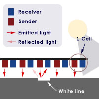
The sensors used in line follower robot are Infrared sensors and they are made with 2 different components:
– a light emitter
– a light receiver
When the emitter emits light, the light is reflected by the floor. If the line is white and the sensor is above the line, the white line reflect all the light, so it permits to understand that the sensor is effectively above the line. Instead if the sensor is over the black surface, the sensor doesn’t reflect the light, so we can understand that the sensor isn’t above the line.
If we have many IR sensors, knowing which sensor is above the line, lets to understand if the robot is going out from the middle of the line, at the right or the left side. In the picture above are shown 5 sensors, but is not unusual to use 8 or 10 sensors. The minimum required is 3 sensor (left, straight, right).
The CONTROL
The robot, mostly if the line is curved, will go out of the path. It is important to teach to the robot how to maintain above the line. Usually, it is possible to do this with a motion control and the PID (Proportional-derivative-integral) control is the most famous. This control will try to compensate the error, i.e. the misalignment from the line. You can find some details about PID in wikipedia.
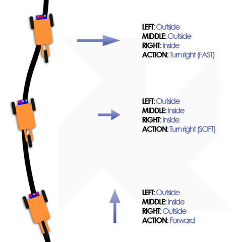
This picture shows the criteria used for the control:
The combined readings from the sensors are used to understand if the correction done by the control have to be hard or soft.
Linea – The line follower robot
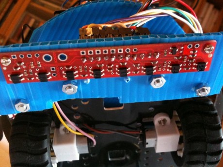
This robot was shown on the Arduino Day, in Rome (Italy), in April 2011 and use a Pololu sensor with 8 IR leds ( link), very cheap (14 euros). It is offered with an Arduino library, made by Pololu. This library resolves all the interfacing problems with Arduino (yeah!).
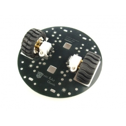
The robot chassis is build using a cheap DFRobot module (link) that for less than 30 euros, offers also 2 gear motors, 2 motor supports and 2 wheels:
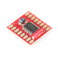
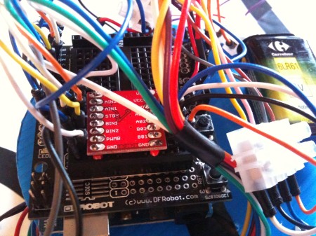
 The motor driver is a Sparkfun module (link) , very very cheap (8 euros), that can feed up to 1.2A. It supports 2 gear motors and lets the PWM usage.
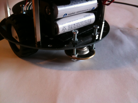
 For my convenience I assembled the motor drivers on a breadboard shield, but it is enough a normal breadboard. Others components (ball caster, sensor support, batteries) are self made or bought in a hardware shop.
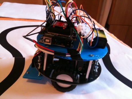
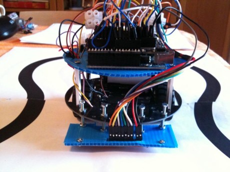
This is Linea:
Here Linea in action:
This is the code used:
#include <PololuQTRSensors.h>
// motor driver pin
#define out_STBY 6
#define out_B_PWM 9
#define out_A_PWM 3
#define out_A_IN2 4
#define out_A_IN1 5
#define out_B_IN1 7
#define out_B_IN2 8
#define motor_A 0
#define motor_B 1
#define motor_AB 2

#define NUM_SENSORS 8 // number of sensors used - numero di sensori usati
#define TIMEOUT 2500 // waits for 2500 us for sensor outputs to go low - aspetta 2500 us prima di mandare low i sensori
  //define QTR pololu sensor
PololuQTRSensorsRC qtrrc((unsigned char[]) {2, 12, 11, 10, 17, 16, 15, 14}
 , NUM_SENSORS, TIMEOUT, 255);
unsigned int sensors[NUM_SENSORS];
  void setup()
{
  Serial.begin(115200);
  // define motor drive output pin - definisci i pin di output del motore
  pinMode(out_STBY,OUTPUT);
  pinMode(out_A_PWM,OUTPUT);
  pinMode(out_A_IN1,OUTPUT);
  pinMode(out_A_IN2,OUTPUT);
  pinMode(out_B_PWM,OUTPUT);
  pinMode(out_B_IN1,OUTPUT);
  pinMode(out_B_IN2,OUTPUT);
  motor_standby(false);// motor stand-by off and stop - togli i motori dallo stand-by e fermali
  stopMotors();
  delay(2000);
  SensorCalibration(); // sensor calibration - calibra i sensori
  delay(2000);
}

void loop()
{
  follow_segment(); // follow the black line - segui la linea nera
}
// PID parameters
int Kp=120;
int Ki=100;
int Kd=100;
// follow the black line - segui la linea nera
void follow_segment()
{
  int last_proportional = 0;
  long integral=0;
  int primo=0;
  int posizione = qtrrc.readLine(sensors); // read the IR sensors - leggi i sensori IR
  long int proportional = posizione;
  int P = proportional * Kp/1000; // Proportional parameter
  long int derivative = proportional - last_proportional; //Derivative parameter
  if (primo==0) // firt cycle set derivative to zero - al primo giro imposta il derivativo a zero
     {
      primo=1;
      derivative=0;
    }
  int D=derivative*Kd/1000;
  integral += proportional;
  int I=integral*Ki/1000; //integral parameter
  // Remember the last position - ricorda l'ultima posizione
  last_proportional = proportional;
  int PID =P + I + D; //calculate the PID
  // print some values on the serial port - scrivi qualche valore sulla seriale
  unsigned char zz;
   for (zz = 0; zz < NUM_SENSORS; zz++)
    {
      Serial.print(sensors[zz]);
      Serial.print(' ');
    }
    Serial.print(" position: ");
    Serial.print(posizione);
    Serial.print(" P:");
    Serial.print(P);
    Serial.print(" I:");
    Serial.print(I);
    Serial.print(" D:");
    Serial.print(D);
    Serial.print(" PID:");
    Serial.print(PID);
  // set the values for the motors based on the PID gain - setta i valori del motore basati sul PID
    const int maximum = 40; // the maximum speed
     if (PID > 0){
       if (PID > maximum) PID=maximum;
       motor_speed2(motor_B,maximum);
       motor_speed2(motor_A,maximum-PID);
      Serial.print(" Motore_B:");     Serial.print(maximum);
    Serial.print(" Motore_A:");      Serial.print(maximum-PID);
      }
      else {
       if (PID < -maximum) PID=-maximum;
       motor_speed2(motor_B,maximum+PID);
        motor_speed2(motor_A,maximum);
      Serial.print(" Motore_B:");     Serial.print(maximum+PID);
    Serial.print(" Motore_A:");      Serial.print(maximum);
      }
      Serial.println("");
}
// ------------------ stop the robot - ferma il robottino -----------------------
void stopMotors(){
  motor_brake(motor_A);
  motor_brake(motor_B);
}
// ------------------ Motor driver mgmt routines - routine per gestire i motori -----------------------
void motor_speed2(boolean motor, char speed) { //speed from 0 to 100
  if (motor == motor_A)
   speed = -speed;
  byte PWMvalue=0;
  PWMvalue = map(abs(speed),0,100,50,255); //anything below 50 is very weak
  if (speed > 0)
    motor_speed(motor,0,PWMvalue);
  else if (speed < 0)
    motor_speed(motor,1,PWMvalue);
  else {
    motor_coast(motor);
  }
}
void motor_speed(boolean motor, boolean direction, byte speed) { //speed from 0 to 255
  if (motor == motor_A) {
    if (direction == 0) {
      digitalWrite(out_A_IN1,HIGH);
      digitalWrite(out_A_IN2,LOW);
    } else {
      digitalWrite(out_A_IN1,LOW);
      digitalWrite(out_A_IN2,HIGH);
    }
    analogWrite(out_A_PWM,speed);
  } else {
    if (direction == 0) {
      digitalWrite(out_B_IN1,HIGH);
      digitalWrite(out_B_IN2,LOW);
    } else {
       digitalWrite(out_B_IN1,LOW);
      digitalWrite(out_B_IN2,HIGH);
    }
    analogWrite(out_B_PWM,speed);
  }
}
// stand-by motor
void motor_standby(boolean state) { //low power mode
  if (state == true)
    digitalWrite(out_STBY,LOW);
  else
    digitalWrite(out_STBY,HIGH);
}
// stop the motors
void motor_brake(boolean motor) {
  if (motor == motor_A) {
    digitalWrite(out_A_IN1,HIGH);
    digitalWrite(out_A_IN2,HIGH);
  } else {
    digitalWrite(out_B_IN1,HIGH);
    digitalWrite(out_B_IN2,HIGH);
  }
}
// motors coast - fai girare i motori in folle
void motor_coast(boolean motor) {
  if (motor == motor_A) {
    digitalWrite(out_A_IN1,LOW);
    digitalWrite(out_A_IN2,LOW);
    digitalWrite(out_A_PWM,HIGH);
  } else {
    digitalWrite(out_B_IN1,LOW);
     digitalWrite(out_B_IN2,LOW);
    digitalWrite(out_B_PWM,HIGH);
  }
}
// IR sensor calibration
void SensorCalibration() {
  int counter, i;
  for (counter=0; counter<40; counter++)
  {
    if (counter < 10 || counter >= 30) {
      motor_speed2(motor_A,10);
      motor_speed2(motor_B,-10);
    }
    else   {
      motor_speed2(motor_A,-10);
      motor_speed2(motor_B,10);
    }
    qtrrc.calibrate();
    // Since our counter runs to 80, the total delay will be
    // 80*20 = 1600 ms.
    delay(20);
  }
     // print the calibration minimum values measured when emitters were on
    for (i = 0; i < NUM_SENSORS; i++)
  {
    Serial.print(qtrrc.calibratedMinimumOn[i]);
    Serial.print(' ');
  }
  Serial.println();
    // print the calibration maximum values measured when emitters were on
  for (i = 0; i < NUM_SENSORS; i++)
  {
    Serial.print(qtrrc.calibratedMaximumOn[i]);
    Serial.print(' ');
  }
  Serial.println();
  Serial.println();
  stopMotors();
  delay(2000);
}
#1 by Lucian on 28 May 2013 - 18:29
Quote
thanks.
the code is corect?
i`m trying different values if the cod is corect
#2 by Lucian on 28 May 2013 - 18:15
Quote
and for your sensors
//you can get the raw sensor readings
// (pulse times from 0 to 2500 us) by calling qtrrc.read(sensorValues) instead of
// qtrrc.readLine(sensorValues).
#3 by Lucian on 28 May 2013 - 18:14
Quote
//you can get the raw sensor readings
// (analog voltage readings from 0 to 1023) by calling qtra.read(sensorValues) instead of
// qtra.readLine(sensorValues).
#4 by Lucian on 28 May 2013 - 17:53
Quote
0 256 939 6 17 1000 position: 3250 P:24464 I:0 D:0 PID:24464 Motore_B:40 Motore_A:0
0 232 945 6 22 1000 position: 3271 P:26984 I:0 D:0 PID:26984 Motore_B:40 Motore_A:0
1 173 950 6 22 1000 position: 3331 P:-31352 I:0 D:0 PID:-31352 Motore_B:0 Motore_A:40
2 72 955 8 26 1000 position: 3444 P:-17792 I:0 D:0 PID:-17792 Motore_B:0 Motore_A:40
4 50 952 9 26 1000 position: 3536 P:-6752 I:0 D:0 PID:-6752 Motore_B:0 Motore_A:40
whit K p= 120 and Kd = 100
#5 by robottini on 28 May 2013 - 18:25
Quote
I think you can try with different values.
At the begin only with Kp.
Kp=0.01
Kp=0.1
Kp=1
Kp=10
and see what happen. After you can calibrate the Kd.
Sorry, but the only way is making some test and to see the answer.
#6 by Lucian on 28 May 2013 - 17:49
Quote
void follow_segment()
{
int last_proportional = 0;
long integral=0;
int primo=0;
int posizione = qtra.readLine(sensors); // read the IR sensors – leggi i sensori IR
long int proportional = posizione-2500;
int P = proportional * Kp; // Proportional parameter
long int derivative = proportional – last_proportional; //Derivative parameter
if (primo==0) // firt cycle set derivative to zero – al primo giro imposta il derivativo a zero
{
primo=1;
derivative=0;
}
int D=derivative*Kd;
integral += proportional;
int I=0; //integral parameter
// Remember the last position – ricorda l’ultima posizione
last_proportional = proportional;
int PID =P + I + D;
#7 by Lucian on 28 May 2013 - 17:45
Quote
0 1000 0 0 0 0 position: 1000 P:10144 I:0 D:0 PID:10144 Motore_B:40 Motore_A:0
0 1000 0 0 0 0 position: 1000 P:10144 I:0 D:0 PID:10144 Motore_B:40 Motore_A:0
0 0 0 0 0 0 position: 0 P:-26784 I:0 D:0 PID:-26784 Motore_B:0 Motore_A:40
0 0 0 0 0 0 position: 0 P:-26784 I:0 D:0 PID:-26784 Motore_B:0 Motore_A:40
0 1000 0 0 0 0 position: 1000 P:10144 I:0 D:0 PID:10144 Motore_B:40 Motore_A:0
not working
#8 by Lucian on 28 May 2013 - 13:41
Quote
*6 sensors whit 0 to 1023 value
#9 by robottini on 28 May 2013 - 17:14
Quote
6 sensors, value from 0 to 5000. The zero is at 2500.
value_read_corrected_zero=value_read – 2500; —> value referred to zero
So the proportional term is P=Kp*(value_read_corrected_zero)
The derivative term is D=Kd*(value_read_corrected_zero – value_read_corrected_zero_previuos)
I never use the integral value (I=0)
I hope it is enough to implement the PID. The coefficients Kp and Kd have to be found making some tests.
#10 by Lucian on 28 May 2013 - 13:32
Quote
Hi!
I use 6 sensors whit 0 to 1000 value, white is 1000 and black is 0.
How to calculate PID?
Position is from 0 to 5000 for 6sensors.
Thanks
#11 by robottini on 20 May 2013 - 06:11
Quote
You can see the driver motor pin wiring here:
#define out_STBY 6
#define out_B_PWM 9
#define out_A_PWM 3
#define out_A_IN2 4
#define out_A_IN1 5
#define out_B_IN1 7
#define out_B_IN2 8
The pin name in the motor driver and the digital pin in the Arduino. I.e. STBY 6 means the pin STBY in the motor driver is wired in the digital pin 6 in the Arduino.
#12 by Ramazan Gümüş on 19 May 2013 - 23:00
Quote
I have solved sensor problem. Right now it is working properly. But I would like to ensure if I connected the motor cables properly to arduino uno. What pins did you wire? Thanks for your help.
#13 by robottini on 10 May 2013 - 17:35
Quote
Is the sensor wired with +5V and GND wired with the GND in the arduino?
0 is not a good value. White is 2500 and black il 0, but this is not a good situation.
#14 by Ramazan Gumus on 9 May 2013 - 22:02
Quote
I have still problem with sensor readings I always read from serial
0 0 0 0 0 0 0 0 position: 0 P:0 I:0 D:0 PID:0 Motore_B:40 Motore_A:40
0 0 0 0 0 0 0 0 position: 0 P:0 I:0 D:0 PID:0 Motore_B:40 Motore_A:40
0 0 0 0 0 0 0 0 position: 0 P:0 I:0 D:0 PID:0 Motore_B:40 Motore_A:40
0 0 0 0 0 0 0 0 position: 0 P:0 I:0 D:0 PID:0 Motore_B:40 Motore_A:40
0 0 0 0 0 0 0 0 position: 0 P:0 I:0 D:0 PID:0 Motore_B:40 Motore_A:40
Sensors doesn’t read I think. Do I have problem with sensor and arduino connection? Do you think should do the sensors have an order or not? Could you explain
#15 by robottini on 9 May 2013 - 21:18
Quote
You don’t need to specify that you are using the analog pins as digital. This is made directly by the Arduino IDE when you use the number 14, 15 etc. So there isn’t a line in the code to specify this.
The led pin is used only to switch the qtr on or off . If you don’t wire the pin, the qtr is always on. So i did’t wire this pin.
#16 by Ramazan Gumus on 9 May 2013 - 20:58
Quote
I understand what you mean but, there is one pin more on qtr. Led on pin is used for what. Also which line did you define analog pin as digital on your code. please help me about it?
#17 by Ramazan Gumus on 9 May 2013 - 17:45
Quote
Hi. I didn’t understand your sensor wire connection. Could you explain it little. Because you have defined the sensor pins as PololuQTRSensorsRC qtrrc((unsigned char[]) {2, 12, 11, 10, 17, 16, 15, 14} But on arduino uno board there is no pins of 14,15,16,17 what are the meanings of these. Can you define the qtr sensor pins please
#18 by robottini on 9 May 2013 - 17:57
Quote
The pins 2,12,11,19 are clear. Regarding the others, 17,16,15,15, in the Arduino environment it is possible also to use the analog pins A0,A1…. A5 as digital pins (only in input).
To do this, the mapping is:
A0 -> 14
A1 -> 15
…
A5 -> 19
So when you read pin 14 you to wire the A0 pin (analog 0 pin).
I hope the situation is clear.
#19 by Gabriel Banahan on 19 July 2011 - 11:38
Quote
interessante..