
Recently the famous site evilmadscientist introduced the new art robot called “Axidraw“.I saw the robot in action and it is very similar to the robot I built in the 2015, called “Cartesio”, a 3d printed cartesian robot. So, I decided to publish in open source all the details about Cartesio.
Cartesio is similar to Axidraw, the main differences are:
– Cartesio is a cartesian robot (xy movement) while Axidraw is a type of corexy movement (t-bot I think)
– Cartesio is based on Arduino, while Axidraw is based on the EBB Driver board
– Cartesio has a large working area (40×30), like an A3 paper, while Axidraw has a normal working area (30×20), like an A4 paper.
– Cartesio is 3d printed, while Axidraw is in metal (? this is not very clear watching the pictures)
– Axidraw can write with a fountain pen, Cartesio not (yet)
– Axidraw costs 450$, Cartesio costs 60$. Not bad!
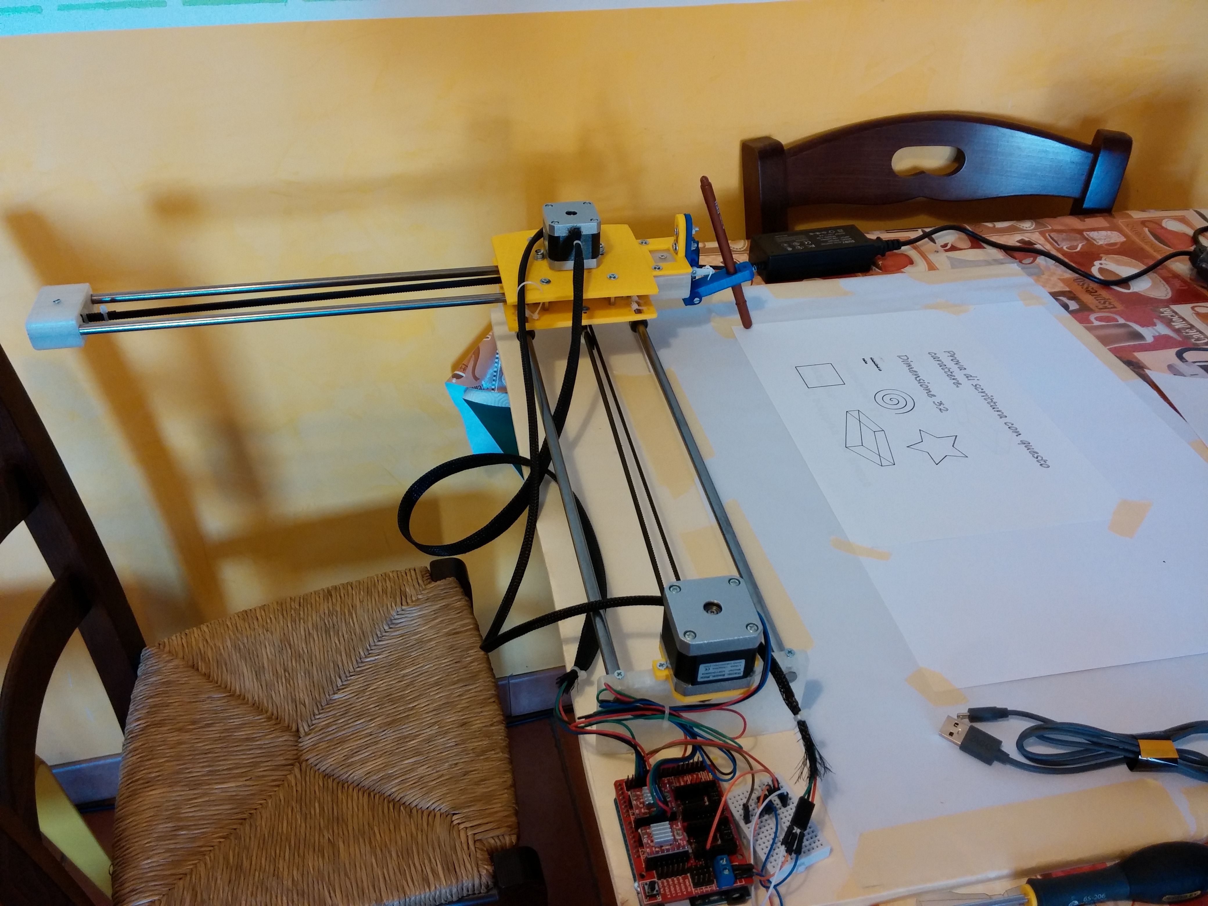
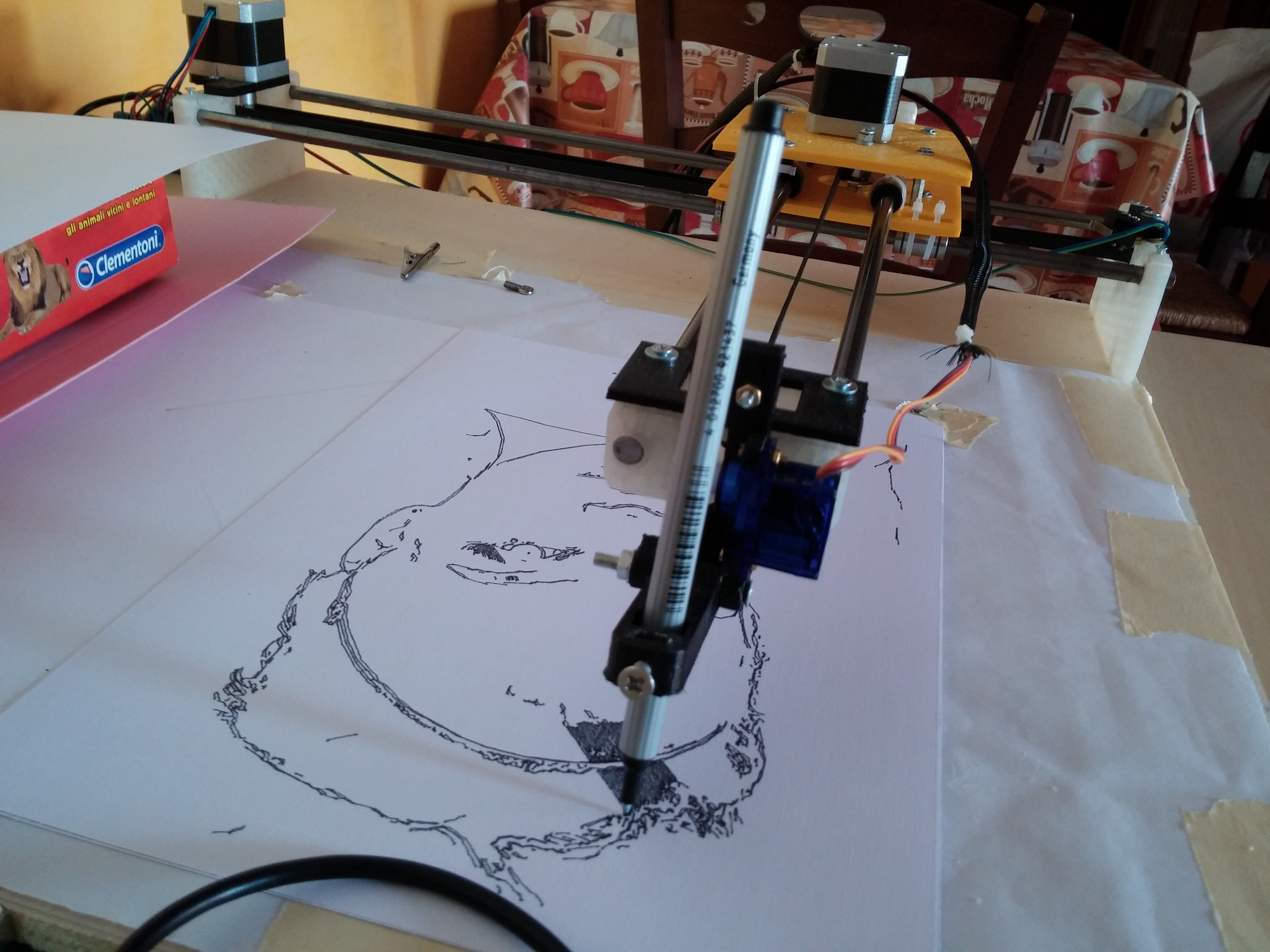
I’m interested in robots that can draw so in the last years I made many drawing robots. Cartesio is the last experiment. I saw a cartesian arm and it was very interesting, so I decided to build one. Here you can see the robot in action:
Here some drawings made with Cartesio.
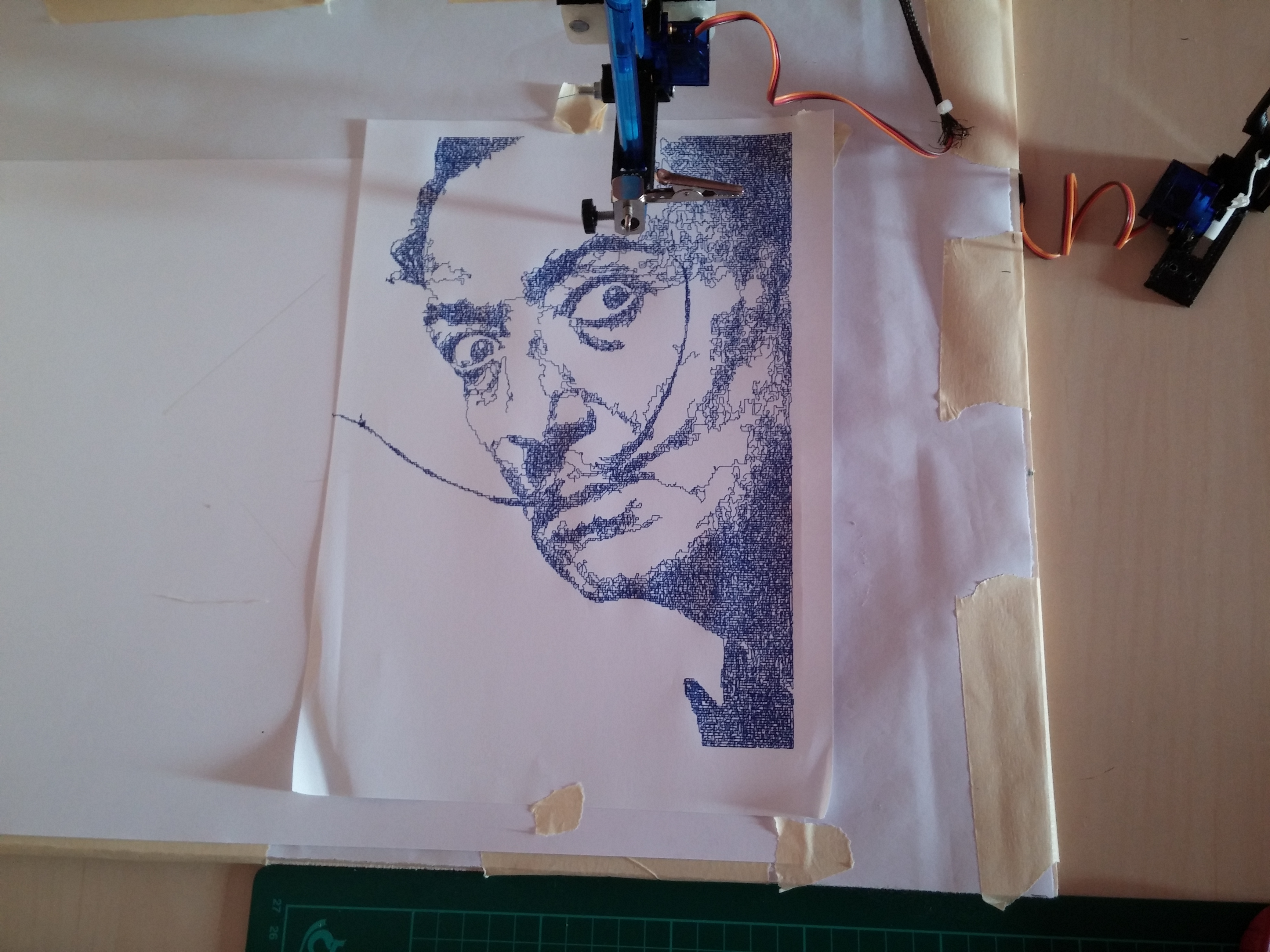


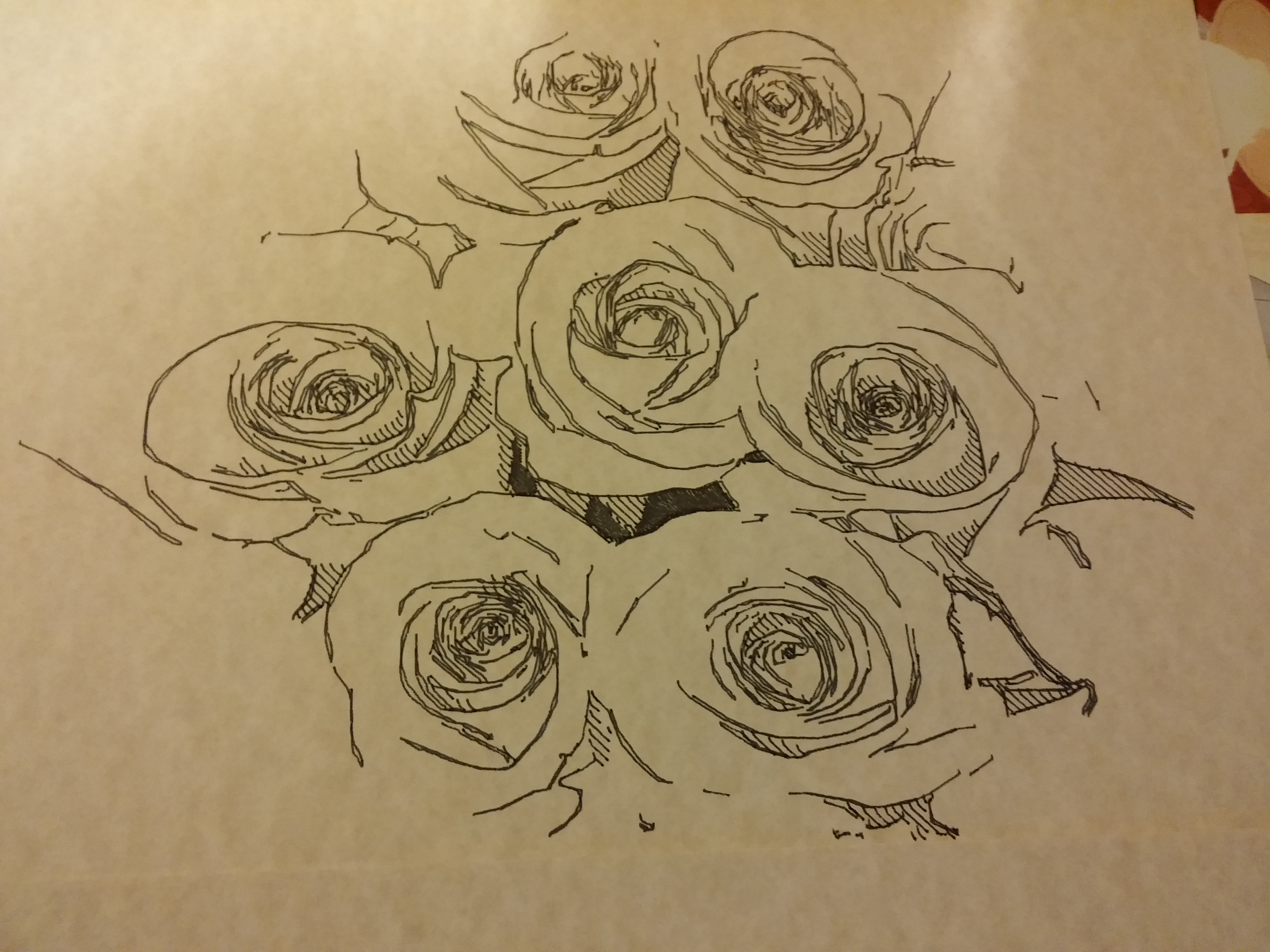
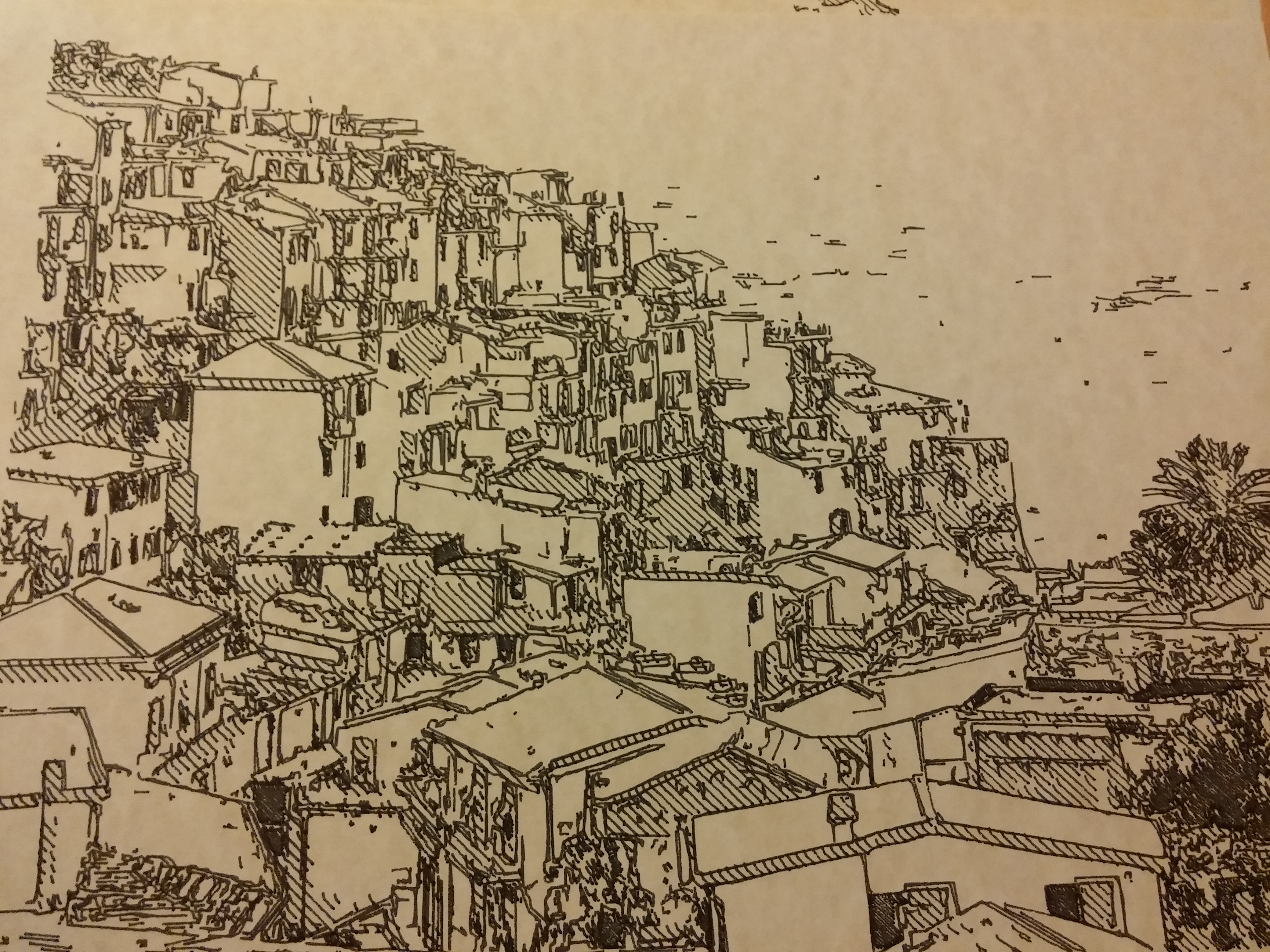


You can find more pictures here.
Hardware:
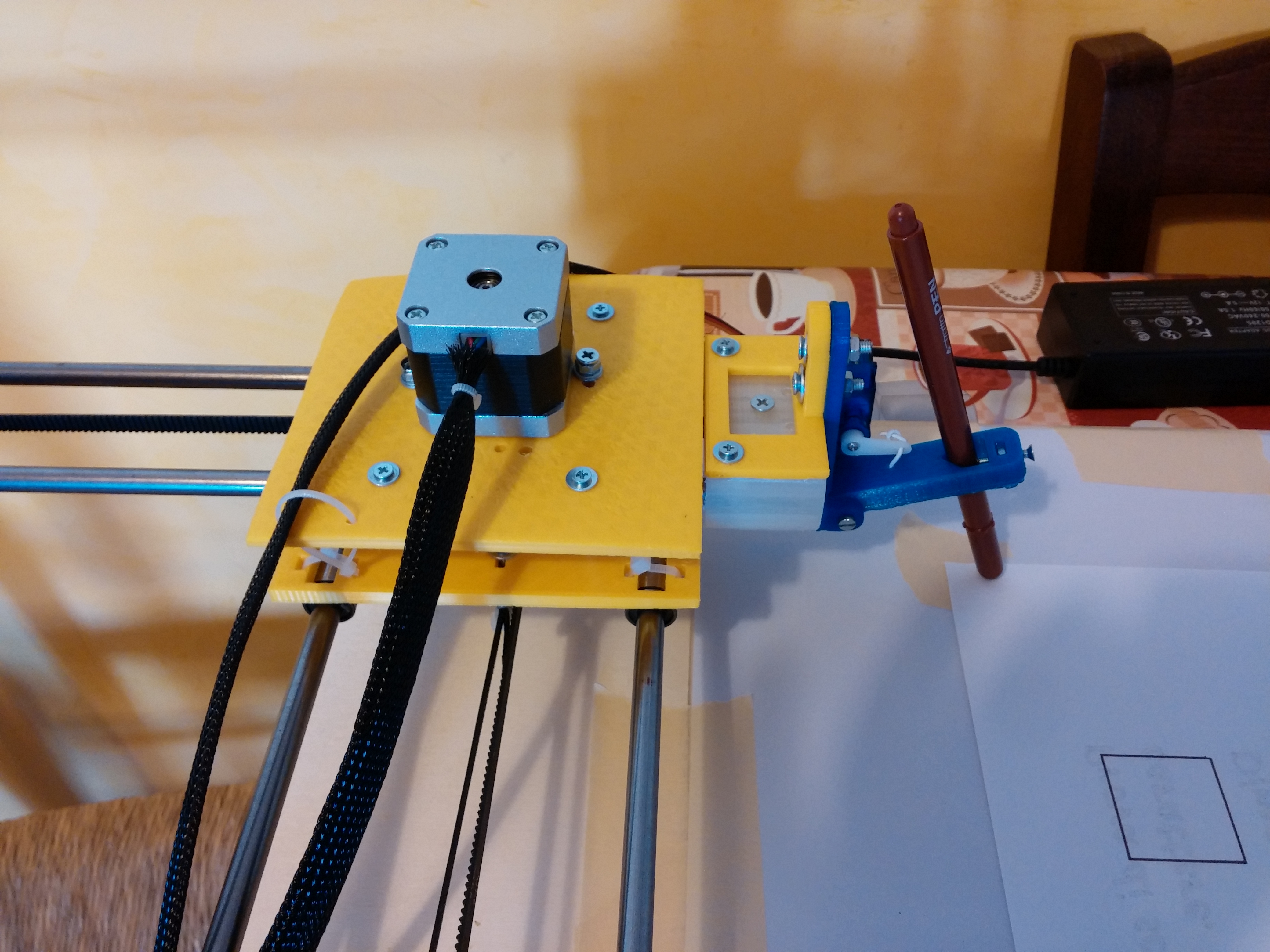
Cartesio is built using M8 smooth rods and LM8UU bearings, GT2 belt, some printed plastics. Standard components, easy to find.
PLASTICS
All the plastics are made with a standard 3d printer (in PLA). You can find the files to print the plastics here.
BOM HW:
– 4x smooth rod M8 – 500 mm – Link
– 4x bearing 624zz – Link
– 8x bearing LM8UU – Link
– 1000 mm GT2 belt – Link
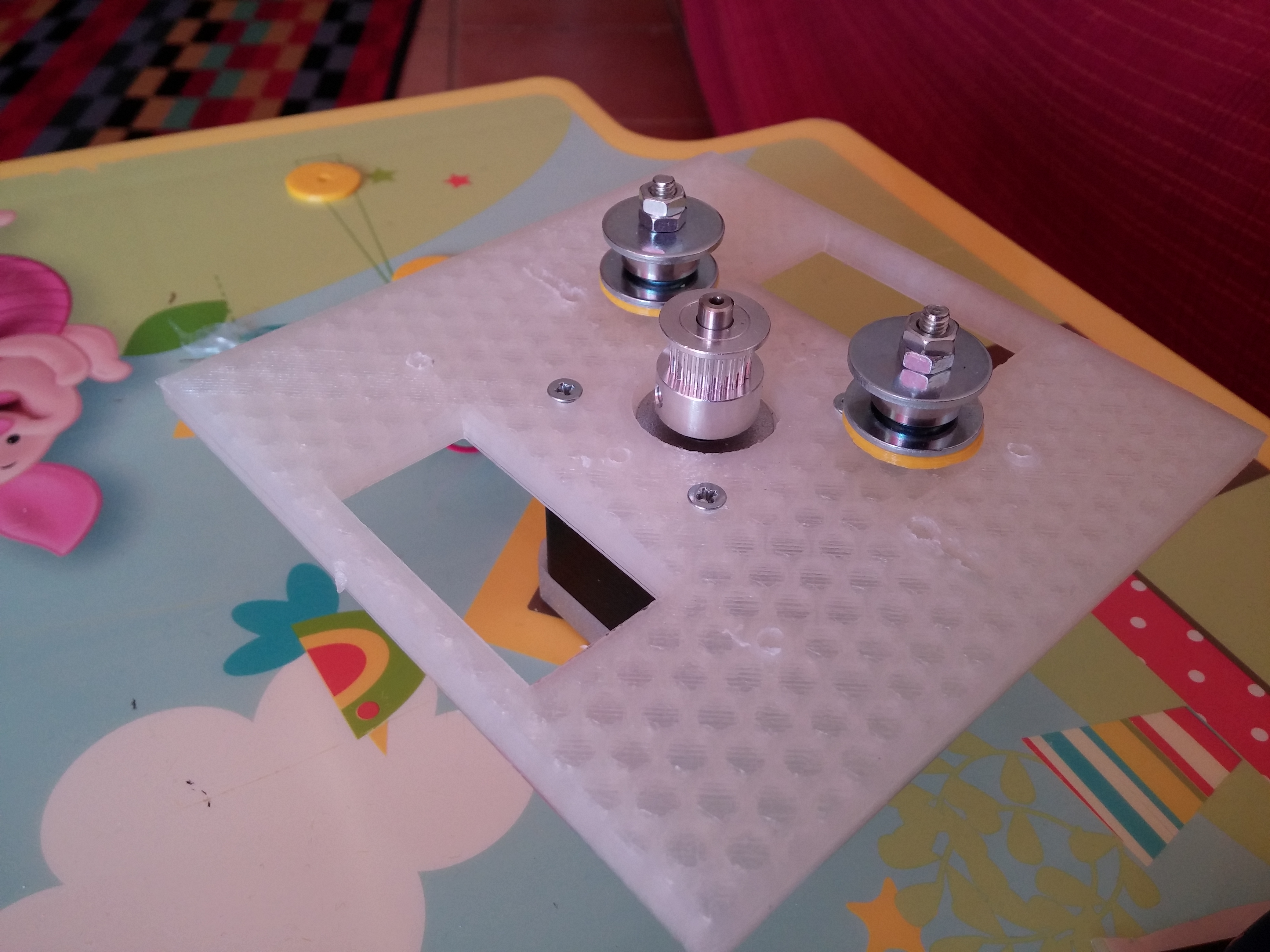
– 2x GT2 Pulley – Link
– 4x M3 spacers 30mm
– M3 and M4 screws and nuts
– some plastic cable ties
– a pen
BOM Electronics:
– Arduino Uno
– Arduino CNC shield – Link
– 2x A4988 driver
– 2 stepper motor Nema17 + wires
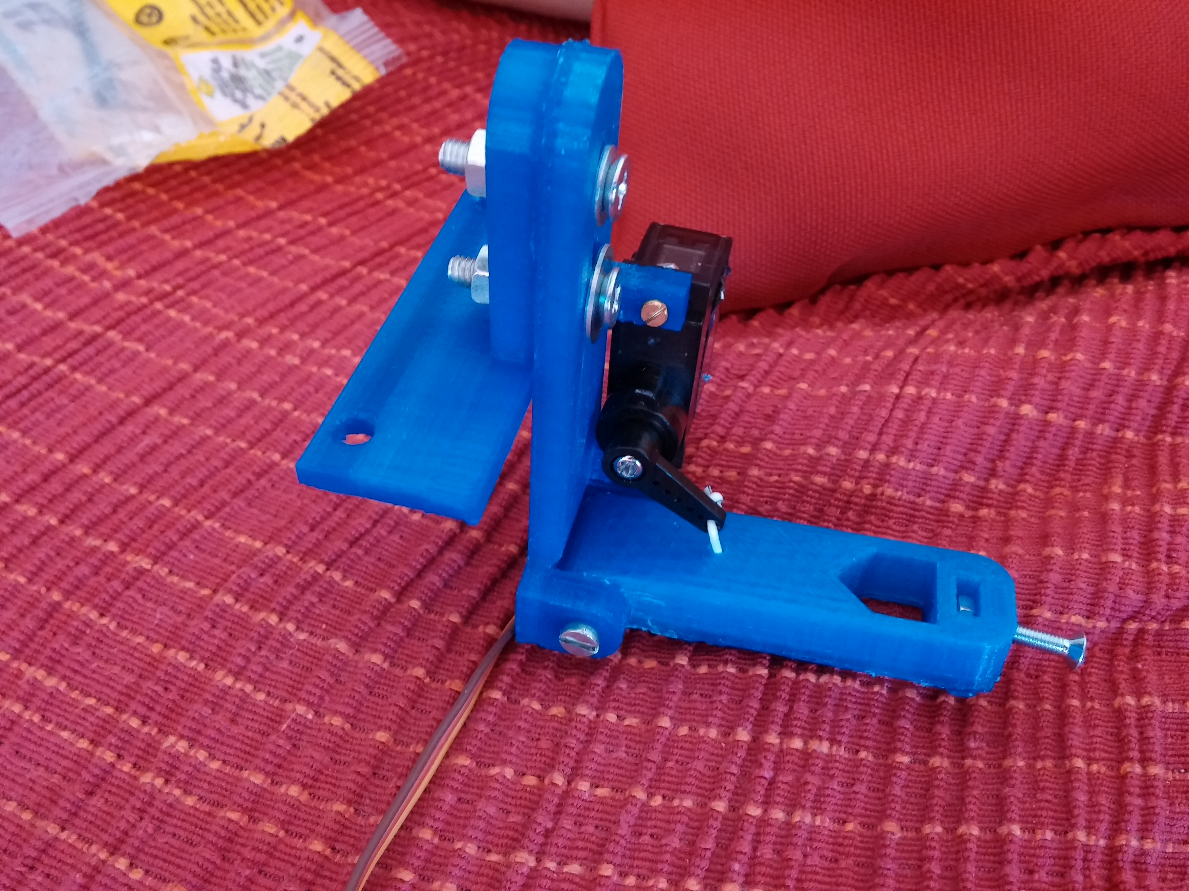
– 1 servo 9g + wires
– 2 mechanical endstop + wires
– 12v 5A power supply
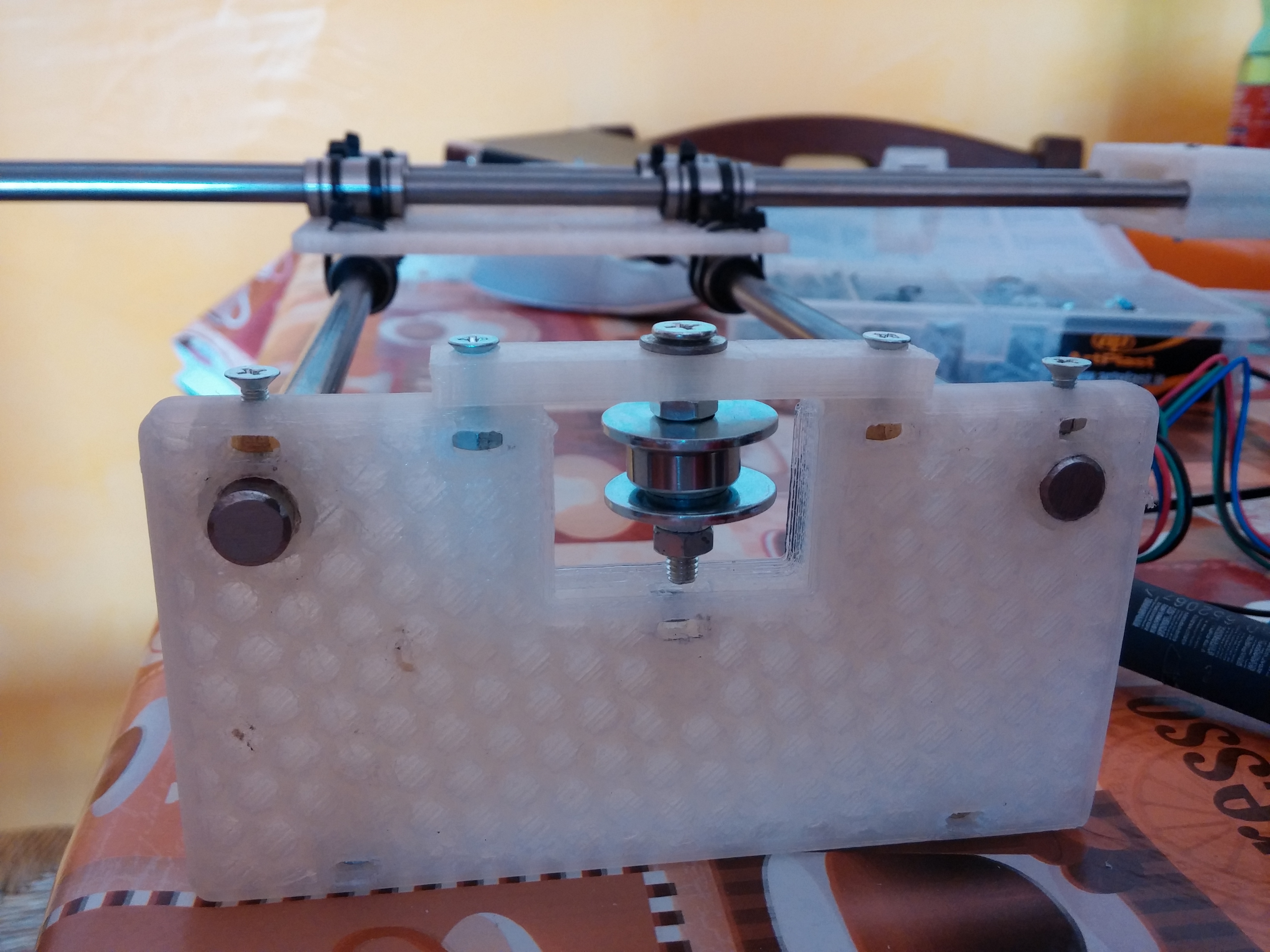
Building
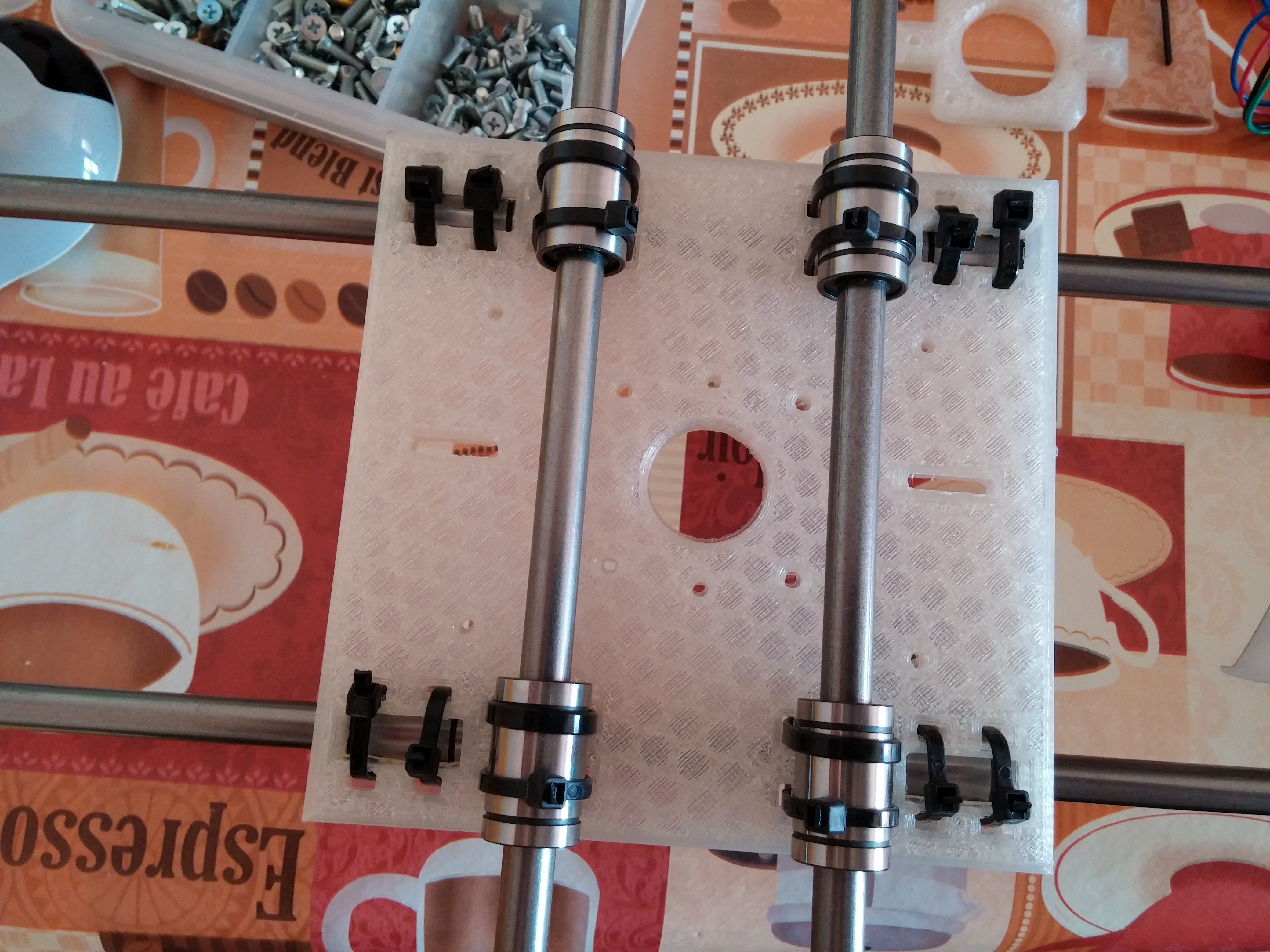
I don’t have a step-by-step building manual, the building is easy if the plastics are well printed. I enclose some pictures that can help to build the plotter.

Software chain
The plotter works starting from an picture or a drawing in order to generate a code (GCODE) that can be put inside the Arduino in order to move correctly the plotter. The process is:
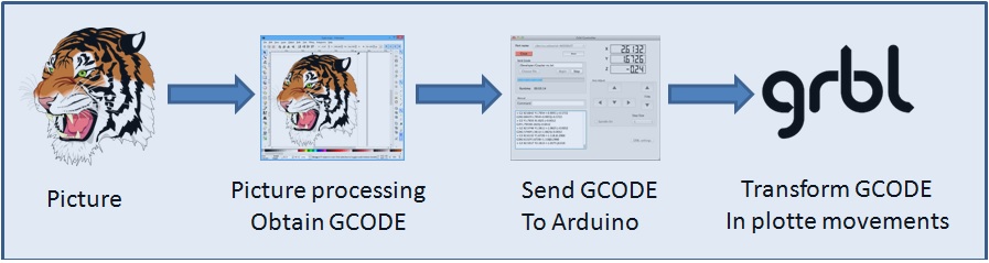
Picture processing to obtain the GCode
I used 3 ways:
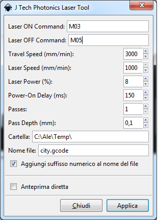
- Inkscape: this open source program can transform a picture or, better, a SVG picture in GCODE. This is possible thanks to a plug-in: J Tech Photonic Laser Tool. Below an example of the usage. You can use M03 to lower the pen (drawing) and M05 to upper the pen (no drawing). Put a value on the field Power-On-Delay (i.e. 150ms) because the servo needs a little time to perform the movement. For the Laser power (%) field see the GRBL section of this tutorial
- Death to Sharpie: This is an amazing sw made by Scott Cooper in Processing that I customized for the plotter. You can see instructions and examples here. You can take the source code customized here.
- Hatch4_Gcode2: This is a simple code made by me. It uses the opencv in Processing. It starts with a canny edge detection and after performs an hatching in the gray zones of the image. You can take the source code here
Send Gcode to Arduino
There are many sw that can send Gcode to Arduino. I use the GRBL Controller, but you can use what you want
GRBL with Servo management
The amazing GRBL is the core of the plotter inside the Arduino Uno. But GRBL has a little problem. It works only with stepper motors and Cartesio has one servomotor to raise the pen. So I made some changes to GRBL to drive a servo motor. In fact this is a fork of GRBL 0.9i and it is published here.
See github to understand how you can change the parameters if you want to customize it.
I post also the GRBL configuration I use for the plotter here.
I hope you have fun building the Cartesio plotter.
Hi, thanks for your project, I have concluded it successfully. But I have a problem, reaching the end of a project the robot begins to draw on the limits of the “Y” axis. It only happens with complex drawings, it doesn’t happen with simple projects. You can guide me. thank you
Hello! congratulation for your project! I like it!! Could you please tell me if this project is (easily) expandable in order to print onto surfaces of at least 500 x 500 millimeters?
Kindest regards!
Alberto
hai i am sarath i have one new idea the setup of you mechanical we can change the polagraphy pls tell it work or not
Found this to be much more helpful!!!
http://www.instructables.com/id/4xiDraw/
Is the BOM correct? I have 1000mm of GT2 belt, but it looks like I need 2 x 1000mm?
If anyone can post a link to a pic of the belt arrangement between the plates it would be a great help to anyone building one of these.
There seems to be more 3D parts in the STL folder than I need??
Thanks for the the great father son project
How do I adjust the page size in hatch 4 gcode
Thanks
hi!!!
i m actually printing the part to make one
nice project
just one question , i want to reduce the size for A4 only
i don t think this is a problem , it can be setup in the arduino code??
thanks again to share your project
Hello I realized the cartesio but I can not get the programs shown to turn from jpeg to g code as the examples shown what i care a lot can you tell me how to do a driving guide?
My plotter drawing only outlines but not filling up spaces viz eye ball etc. But I find your drawings take care of that. I do not know what I am missing.
Please could you explain how the belts are set up, because the pictures above do not show that. Especially under the carriage. I know it’s trivial but please help. Thanks
very pleased with what you did! everything works but, all my drawings are turned 45° no mather what i do :/ can you please help me
I CAN NOT configure the servo, only m03 works, can someone help me?
Good post, keep
I’m having the issue with power on delay option, how to put value in ms or s? whatever I’m putting here it is taking it in seconds. I need to put values in ms in Power-on-delay option. I’ve used different version of this extension, but unable to solve the issue.
Any help would be much appreciated.
please mail me, if there is any solution for that
Your comment is awaiting moderation.
Related to servo movement, it ended working for me using M03 S990 for up position and M03 S590 for down position. I do not know why, but it works.
The only thing I have not managed to control is the homing cycle.
I have read all the instructions given in Github and I cant make it work.
How do I start the Homming cycle? Is it suposed to start alone when powering on, or do I have to “triger” it? I have read that $H command trigers homming, but it gives me no response.
Thanks in advance
Hello, very good job!
I’m having a problem, I use Death_to_Sharpie to generate the G-code then I get this code and I insert the program that reads the G-code called BCNC, it forms the images but of the error when it executes.
What program do you use to run G-code? When I use Inkscape it works great, but I wanted to use Death_to_Sharpie because of the scribble effect in the drawing.
thanks for the help
Can anyone check whether these pins are correct for an Arduino Uno please
Pin 2 = X step
Pin 3 = Y step
Pin 5 = X dir
Pin 6 = Y dir
Pin 8 = Enable
Pin 9 = X end stop
Pin 10 = Y end stop
Pin 11 = Servo
Kind Regards
Also, do you have an image of how the lower carriage is secured to the belt?
Hi i’m a little confused. The parts shown below
http://robottini.altervista.org/wp-content/uploads/2016/03/20150510_092430.jpg
Besides the pulley, the rest don’t seem to be found in your parts list. are they the 624zz bearings?
Can I have a schematic please
I have all the parts servo 9g , nema17 , A4988 , power 12V
But I need a schema to connect all the parts
Kind regards
IThe shield is described in the post. There is also a link to the product
Can I get the schematic of the shield you use
I have all the parts Nema 17 , A4988 , Servo 9G , 12V power
So now i searching for a schematic
Can you please help my
Kind regards
All of you who have problems with servo. I had too. Just delete all your grbl libraries, and install again only grbl servo master. Or you can try installing in another pc or laptop, it would 100% work. But, even I solve this problem, now I`m having problem with X and Y, when I type commands for X or Y, 2 of them are rotating. I dont know why, but I hope you will not experience this.
do you have a website how to install opencv 32bit ? and install library opencv for processing ?
sorry, I get project look like this and this is my first time using opencv 🙂
if you have email you can email me, its very helpful for me.
[email protected]
Thanks
the opencv are a processing library. Please refers to this page: https://processing.org/reference/libraries/
@erison, you have to install first the opencv library for processing. The details are here: https://github.com/atduskgreg/opencv-processing
help me please.
The source code Hatch4_Gcode2 opened in the processing 2.2.1. but if I run the source code I have a message:
No library found for gab.opencv
No library found for org.opencv.core
Libraries must be installed in a folder named ‘libraries’ inside the ‘sketchbook’ folder.
Thanks
Dear Members,
please help me!
I’m very newbie user, with rudimentary language skills. I would like to using the grbl servo, with usual peripherals: two stepper motor (X, Y axis), and one rc servo (Z axis = head moving).
I read this posts, but not clear the setup. My rc servo is a simple tower pro sg90 (180 degree).
How can configure the spindle_control.c file, for goow working?
What is the connection between:
define RC_SERVO_SHORT 15 // Timer ticks for 0.6ms pulse duration (9 for 0.6ms)
define RC_SERVO_LONG 32 // Timer ticks for 2.5 ms pulse duration (39 for 2.5ms)
and the servo duty cycle?
What values can giving the M03 parameters?
My arduino board is uno r3.
Thank you!
I used processing 2.2.1 and I run Hatch4_Gcode2, but can’t run because I get massage:
No library found for gab.opencv
No library found for org.opencv.core
Libraries must be installed in a folder named ‘libraries’ inside the ‘sketchbook’ folder.
Can you help me ?
Mate, the wiring and everything is okey, but we have a problem with servo, hes going in maximum making full 180 degree rotation with M03 S20 or S-Whatever, and he don`t come back with M05. What can be the problem here? I even changed the servo, but same again. Can it be from 5V power from CNC Shield ?
Ok, laser mode not needed, but contrrolling the servo is still imposible.
And do I have to put grbl in laser mode?
Thanks.
Thank you for the early response, but, unfortunatellty I tried what you said and it does not work.
In fact, when typing comands throw the comand line, S05 moves the servo to a midle position more or less, and the servo does not react to M03 S200, for example. It only works between M03 S600 and M03 S900 and sometimes moves to one end and gets stuck there.
How I can solve this? I have tried five different servos and it does the same.
Thanks in advance.
Pd : The comands generated by J Tech photonics laser tool are like M03 S200 S8 and S05 S0 or something like that. is it ok?
Hello,l great design. I have done one similar plotter and I was attempting to use your grbl and inkscape with J Tech Photonic Laser Tool. How do I adjust servo movement, I mean up and down position.
Thanks
In this window: https://jtechphotonics.com/wp-content/uploads/2015/01/J-Tech-Laser-Tool.jpg, use in the field “Laser ON command” the value M03 Sxxx (xxx between 0 and 255) to rotate the servo between 0-180. In the field “Laser OFF command” use S05.
hi. ı can not Picture processing to obtain the GCode. Please help me.
Thank you, Robottini!
I ordered everything but nuts and bolts which I can get it locally and plastic parts. I will stick with 50 cm as you recommended.
I see your photo do you have other photo? Any info to see the step will be helpful for me.
How does the machine know if the belts are set up for corexy or XY movement?
Thank you for your quick response!!
One more question. If I get longer smooth rod, the area where the plotter can move simply gets larger. Correct?
If so, can you think anything I should be careful (length of wire, or belt maybe?)?
If you get more longer rod, the weight is important and the rod bends. In my opinion 50 cm is the limit.
Thank you for showing this! I want this as a Christmas gift for my husband.
I want to make sure to get the parts correctly. If you can clarify the details, I really appreciate it.
1) Bearing (flanged or anything specific?),
2) Spacer should be round?,
3) Driver; http://www.microcenter.com/product/442468/A4988_Stepper_Motor_Driver
4) Stepper motor; https://www.adafruit.com/product/324
5) Servo; https://www.amazon.com/TowerPro-SG90-Mini-Servo-Accessories/dp/B001CFUBN8
6) mechanical endstop; https://www.amazon.com/Signswise-Mechanical-Endstop-Printer-Makerbot/dp/B00TDFBLJW/ref=sr_1_2?s=industrial&ie=UTF8&qid=1481488236&sr=1-2&keywords=mechanical+endstop
7) Power supply; https://www.amazon.com/TNTE-12-Volt-Power-Supply/dp/B009ZZV6TA
I can’t wait to see these come all together!
1) bearings are not flanged. Plane.
2) Spacers are round
3) the A4988 is ok. If you see on ebay or aliexpress you can find the driver for 2-3$
4) ok
5) ok
6) ok
7) ok
Good luck!
Does your grbl_cartesio support corexy?
Yes
Hello, when you write “mechanical endstop” are you referring to some like this: https://www.lulzbot.com/store/parts/mechanical-endstop-switch ?
Another question; is really simple as you said to build this plotter ?
For the mechanical endstop, yes.
This is not a plotter for a noob. I don’t provide a detailed manual to build the plotter. For skilled people it is easy to build, if this is your first building, please, don’t begin.
Hi, i did it, but the servo is not working good. When i type M03 S20 he rotates, but when i type M05 he is not rotate back. What is the problem can u help me ?
Are you using a little servo (9 gr.) or not? Because if you use a big servo, you have to provide an external power supply (5v). Arduino can’t provide high current for big servo.
Hi, i build cartesio but i have problem with servo is problem then i set command M03 servo is going up but when I set command M05 servo is not down. how to solve this problem.
Are you using a little servo (9 gr.) or not? Because if you use a big servo, you have to provide an external power supply (5v). Arduino can’t provide high current for big servo.
Hi, i build cartesio but i have problem with servo is problem then i set command M03 servo is going up but when I set command M05 servo is not down.
Please send [email protected]
there is a link for the firmware inside the post
Please can you explain how the belts are set up ,especially the x-axis beneath the carriage.
Congratulations for the project. I am making one using all your data but have a speed problem.
G0 and G1 move fast but G2 and G3 slow. I mean, the movements for circles or part of circles are very slow in comparison to rectilinear moves. I have never seen that in your or other movies of this machine.
Does anybody have the same problem?
Thank you
Carlos
Hello. Congratulations for the project. I made one but have a speed problem when the machine executes circular moves. Too slow. Rectilinear moves are ok, but circles or parts of circles are drawn as lot of segments and the pen moves very slowly. I use the firmware you suggest and grbl manager for connecting pc and machine. Any help will be appreciated. Thank you.
The shield is good, but you need to configure the jumpers for 16 microsteps.In the picture http://1.bp.blogspot.com/-R9x3jUTxT64/VR-szVT9fWI/AAAAAAAAJAo/Orf0Byhv820/s1600/kk.png you can see how configure the jumpers.
Are u saying i should wire all that 12 pins (6 of x and 6 of y) to the ground pins ?
I`m using this CNC shield ” https://www.aliexpress.com/item/Free-Shipping-4-x-A4988-Stepper-Motor-Driver-with-Heat-Sink-UNO-R3-Board-CNC-Shield/32464507854.html?ws_ab_test=searchweb201556_6,searchweb201602_4_10036_10035_10034_507_10032_10020_10001_10002_10017_10010_10005_10011_10006_10003_10021_10004_10022_10009_401_10008_10018_10019,searchweb201603_8&btsid=9a25da36-bcdd-4049-a050-789131c3dd81 ” u gave this link in BOM Electronics parts, A4988 drivers too
Hi mate, i build all of this beautiful stuff. I wired the steppers, wired servo like its in photo, installed the Grbl which i take from your link, uploaded, go to Universal Gcode sender, steppers are working, but if i write in Command X1 or Y1, a pen goes 5cm. Can u help me ?
Hi, Are you sure you are using the microsteps???
See this picture: http://1.bp.blogspot.com/-R9x3jUTxT64/VR-szVT9fWI/AAAAAAAAJAo/Orf0Byhv820/s1600/kk.png
thank you. I will investigate a little to see if I can get it
First of all congratulations for the project from Spain.
My serious question if you could make autonomous, ie adding a SD reader to load the image from the card.
Thank you and congratulations again
With the GRBL there ins’t the support to SD Card. You can try to adopt Marlin, but you need to customize for the plotter. You can find some tutorial with google about it.
How you wired the Servo in CNC Shield ?
ni on 6 May 2016 – 07:18
The servo motor is connected to +5v,gnd for the power and to z+ endstop for the signal.
I post a picture:
http://robottini.altervista.org/wp-content/uploads/2016/05/arduino-cnc-shield-wiring.jpg
How to connect servo 9g?
Hello, could you clarify which files and how many of each I need to print? It looks like some of them are the same or serve the same purpose.
please frimware [email protected] send
axidrow
the firmware il linked in the post
hello,
really appreciable work!,i just wanted to know why is Arduino CNC shield used?
thanks in advance!
Hi,
Whether it is possible to compile the source code for atmega32?
Hi, i build cartesio but i have problem with setup servo, and steps/mm in grbl controller, with servo is problem then i set command M03 servo is going up but when I set command M05 servo is going still up not down.
Problem with stepps/mm is then I manualy move with x or y axe for example 10 mm it move for example 3-5 cm
Can you please write little manula how to set up cartesio,
(sorry for my english)
Heard from many people that first time users of sg90 got into trouble of burning their sg90 servos or servo gets stuck with no clue what to do further…..
Exactly ! we also had a burnt sg90 servo during first time experiment.
Thought of sharing our experience and sort of solution to get out of it. May be it can help.
If you have symptom of the servo got hot and you did not notice it for long time, (may be 5 to 10 min) then you might have already ruined the servo , throw it away and get a new one before going further.
We bought a new sg90 servo same make and used it as below and it works fine after that.
With below steps we were able to success fully run the servo through grbl. It is bit tricky to get it right !! with trial and error.
1. First you find the proper angle of movement fo the servo’s arm wrt to the command you are issuing ,
2. To find the proper angle of movement , connect +5V DC from a regulator power supply (if you have a current controlled DC power supply that will be best to cut the power off automatically when the servo
erratically revolves beyond it mechanical limits when we issue command to move through arduino and it may draw extra current and get hot and damage itself before you notice it ).
3. Now dont mechanically connect the servo to any part of pen movement assembly, just keep the servo as it is with the horn (this horn should have come along with servo when you bought it)
assembled on it and horn not connected mechanically to anything.
4. You switch off power and set the horn of the servo to the middle with hand and give power from 5V DC power supply (with current control set to around 200mA)- issue command M03 S20 you should see the movement of the horn (signal pin of servo connected to the Z+ of CNC shield). Then issue M05 command then you should see the reverse movement of the horn , that is it should go back to the same position it was in before you issued M03 S20.
5.. Repeat this process , until you are satisfied that every time you issue M03 S20 and M05 it goes back and forth to the same position , and ensure you are not on the extremes of the servo movement.
6. In between you can sometimes hear the internal gear assembly trying to move the servo horn to a position until the internal balancing potentiometer in the servo is in track with movement and comes to a stop. That is ok ! as it after all cheap servo !.
7. By initially moving the horn to the middle position by hand( without power ) we have ensured that it will not suddenly move to a extreme with a M03 S20 command (mind these servos work only 180 deg and not 360 deg rotation)and try to move beyond the limits and get hot by drawing excess current and finally kill itself !
And once you are satisfied with the movement – DONOT touch the horn and leave it in the same position and they assemble it in the cartesio pen assembly front end.
Then wire the servo as per the wriing diagram I had attached. By using a separate 7805 regulator, you can avoid the servo not working due to no sufficient power from using the arduino inbuilt 5V regulator particularly when using from laptops (laptops usually dont provide proper 5V current through USB ports) , also if your servo goes into some awkward position and gets hot draws more current , you might probably burn your arduino’s 5V regulator also, a simple external 7805 solves those issues.
I have also attached one 3d printed STL file of a holder I designed , which I made to connect the servo to the pen-up and down movement assembly and tie it up with servo with a small metal string ( a resistor’s metal pin cut should work to tie up the servo horn and the holder. Print it and use it it might help. please see the orientation of the servo and its horn in the hand drawing and as well as my video.
it might help you.
https://drive.google.com/open?id=0B2dLiyhOq0STb2hnMlFwMXdtT1k
You can refer the wiring diagram attached. and also some of the photos and videos can help you.
https://goo.gl/photos/9Nk3nsrggryY1qETA
Please try these steps, it might help. Thanks all the best for your cartesio.
Thanks for your contribution!
Hi,
Could you provide more details how to connect belts? There are two belts or there is only one. Something like corexy?
Do I need breadboard? I thougth that arduino uno plus cnc shield is enough is enough 12v 5a from old laptop?
Do you have idea how to modify it for two colors drawing? With two pens…
hi, thanks but i think i did it (but not sure when i watch this picture https://www.flickr.com/photos/64388698@N07/19469602283/in/album-72157656058658989/)
it seems that the servo is wire on the breadboard. Did you use a motor chip to use it .What are all these wiring on it ? Really don’t understand where i made it wrong.
Thanks for helping man
@t3v. Yes in the first version of Cartesio, I din’t have a working version of GRBL with the servo. So I used an external chip (attiny85) to generate the PPM to drive the servo. In the final version this is not required, because I found a way to drive the servo directly from the GRBL shield.
which code should i use either cartesio or servo master and and which software to generate g code i am totally confused please help me out. is there any way to use atmega 2560 and ramps 1.4 instead of atmega 328p.
@arun: you can use the atmega2560 and ramps 1.4, but you have to modify the configuration of GRBL. Please, refer to GRBL wiki to do this.
To generate the GCODE you can use one of 3 methods explained in the post.
Hi,
i try to did it but got issues with the servo.
I used this http://robottini.altervista.org/grbl_cartesio firmware and when we try to move servo the nema 17 on X axes make sounds and warm up.
Hi,
i try to did it but got issues with the servo.
I used this http://robottini.altervista.org/grbl_cartesio firmware and when we test pins on cnc shield it appears that’s the x+ and X- that’s connected with pin 11. And when we try to move Z axe the X axes sounds to try to move on.
Did you have an explanation ?
Check the wiring for the motor. You can see the wiring for the D11 here:http://robottini.altervista.org/wp-content/uploads/2016/05/arduino-cnc-shield-wiring.jpg
What are the characteristics of stepper motor Nema 17 ?
What are your default options grbl? ($1 ….)
Could you explain to idiots like me how to run Hatch4_Gcode2 and Death to Sharpie. Thank you very much.
1. Cartesio with GRBL – arduino UNO CNC shield worked fine with my desktop machine (AMD/win10) with even 5 hours of continues drawing with no issues at all. But when we tried with our DELL laptop E5400 it (the universal Gcode sender) used to mysteriously stall after around 20 minutes of drawing. Broke our heads with different combinations to find the reason , and found the solution !. It was due to the laptop’s USB port power management feature UGS just does not respond after 20 min of operation even though it was streaming the G-code to Arduino before that !.After doing below steps now my laptop also works for hours of drawing with no problems. Thought of sharing.
Goto Device manager > Universal Serial Bus controllers > USB Root Hub > Right click > properties > power management > uncheck “allow the computer to turn off this device to save power”.Problem solved.
2. Some more pictures drawn by our Cartesio –
https://goo.gl/photos/NfXjMAkygZeQk1qq7
3. Want to understand , is there any other tool chain somebody knows which can generate g-code of a letter or document which is typed in say in microsoft word or any such document so that letter or document can be “written” by cartesio (no hatching or no squiggling required) just plain letter writing by the cartesio’s pen (generate g-code and send through UGS to Cartesio GRBL arduino).can anybody suggest a way.Thanks
awesome, i have did it, .
where can i connect 2 mechanical endstop to arduino cnc shield ?
thanks
Congratulations for your work, I wonder what the pin that is connected servo motor and where can I change the value of the constant.
From already thank you very much.
The servo motor is connected to +5v,gnd for the power and to z+ endstop for the signal.
I post a picture:
http://robottini.altervista.org/wp-content/uploads/2016/05/arduino-cnc-shield-wiring.jpg
Can you give me some pictures showing wires setting with arduino ,
Hi Robottini
My name is thai. i love your machine, i want to make it. but i don’t know about electric, can you help me ?
Thank you
( sorry about my english)
Hi Robottinni,
great machine,works perfect but a have problems with Hatch4_Gcode2,
the generated gcode doesn’t run on controller,Death to Sharpie works perfect,any solution?
Thanks
Hi,I have tried to use the plug-in of Inkscape to convert text, but it didn’t work out, The Gcode files generated by the command are very few, I don’t know what reason be?
Hi Draj,
I’m very happy for you and you children!!! You robot is beautiful and well done. This is the open source philosophy and it is amazing for me share with people in the other part of the world this passion for robots.
Hi Robottini
Success !! We did it – me , my son and my family was so excited when we saw our cartesio which we built started drawing our traditional south indian kolam in the paper (https://en.wikipedia.org/wiki/Kolam)
Your mechanical and software design is very good , simple but effective ! thanks for sharing.
Like to give some glimpse of drawings it drew and it is drawing now (we waiting for the bot to finish the IRONMAN !! – children will love it !!
https://goo.gl/photos/wJMq6Vi9GRHp2TWRA
Thanks once again.
Hi there,
I can’t open the URL of the source code.Could you send it to my email?
Thanks so much!
Hi robottini, Great, yes you are right version 2.2.1 processing works fine. Thanks ! (that too particularly 32bit version worked fine ! , I was trying 2.2.1 64bit version it did not give any response after selecting the JPG file)
Anyway thanks for the great job ! and the heart for sharing !. since the software worked now, me and my son are excited and we are building the plotter (almost all required 3d printed parts are printed ) , we will assemble run the plotter fully and let you know. Thanks once again..
Attempting to use your “Hatch4_Gcode2:”
But there are errors coming during execution. Can you please help in this.
Windows 10 – 64bit
Processing: 3.0.2
OpenCV for Processing 0.5.2 by Greg Borenstein
issue 1:
When we try to RUN the Hatch4_Gcode2 it throws a error
“Please fix the size() line to continue”
Tried to put in below line under Setup
size(700,400,JAVA2D);
issue 2 :
Now the above error does not come and it asks for the file to process.
We shown 34.jpg file given along with the zipfile
But now the window Hatch4_Gcode2 open up and computer does not do anything ! (but it is not hanging)
Can you please help , where we are going wrong.
Thanks. I will fix it. If you use the processing 2.x it works. I just tried whit the 2.2.1 version and it works fine.
Awesome! I like the Cartesio very much and would try to build my own.
Could you please also add the CAD files of the printed parts to thingiverse?
That’ll be great 🙂
Another take on the same subject https://www.youmagine.com/designs/4xidraw
Thanks Miguel, very good job!!!
Very cool !
I like the name 🙂
Fantastic! Had just started the CAD for an Axi draw clone, you’ve saved me a job! Any chance you can post the CAD files, would like to tweak it to suit 6mm rods, as I already have these.
Hi! I like it.
Why you dont use type of corexy movement?
What i can change your code to use corexy movement?
Thank you!
Yes, you can use the corexy, in the t-bot version. The last version of GRBL support the corexy. You can try.