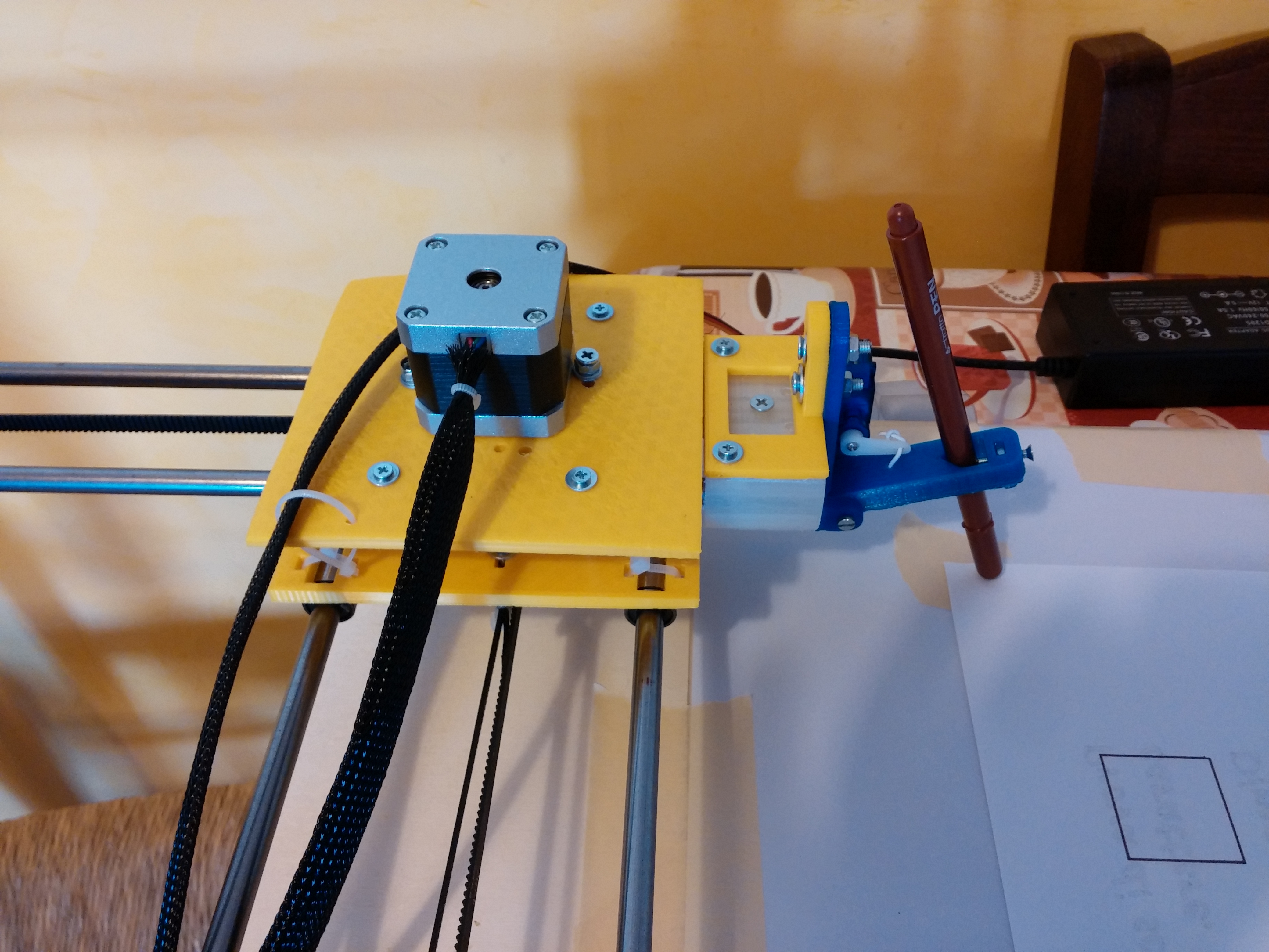
Recently the famous site evilmadscientist introduced the new art robot called “Axidraw“.I saw the robot in action and it is very similar to the robot I built in the 2015, called “Cartesio”, a 3d printed cartesian robot. So, I decided to publish in open source all the details about Cartesio.
Cartesio is similar to Axidraw, the main differences are:
– Cartesio is a cartesian robot (xy movement) while Axidraw is a type of corexy movement (t-bot I think)
– Cartesio is based on Arduino, while Axidraw is based on the EBB Driver board
– Cartesio has a large working area (40×30), like an A3 paper, while Axidraw has a normal working area (30×20), like an A4 paper.
– Cartesio is 3d printed, while Axidraw is in metal (? this is not very clear watching the pictures)
– Axidraw can write with a fountain pen, Cartesio not (yet)
– Axidraw costs 450$, Cartesio costs 60$. Not bad!
I’m interested in robots that can draw so in the last years I made many drawing robots. Cartesio is the last experiment. I saw a cartesian arm and it was very interesting, so I decided to build one. Here you can see the robot in action:
Here some drawings made with Cartesio.
You can find more pictures here.
Hardware:
Cartesio is built using M8 smooth rods and LM8UU bearings, GT2 belt, some printed plastics. Standard components, easy to find.
PLASTICS
All the plastics are made with a standard 3d printer (in PLA). You can find the files to print the plastics here.
BOM HW:
– 4x smooth rod M8 – 500 mm – Link
– 4x bearing 624zz – Link
– 8x bearing LM8UU – Link
– 1000 mm GT2 belt – Link
– 2x GT2 Pulley – Link
– 4x M3 spacers 30mm
– M3 and M4 screws and nuts
– some plastic cable ties
– a pen
BOM Electronics:
– Arduino Uno
– Arduino CNC shield – Link
– 2x A4988 driver
– 2 stepper motor Nema17 + wires
– 1 servo 9g + wires
– 2 mechanical endstop + wires
– 12v 5A power supply
Building
I don’t have a step-by-step building manual, the building is easy if the plastics are well printed. I enclose some pictures that can help to build the plotter.
Software chain
The plotter works starting from an picture or a drawing in order to generate a code (GCODE) that can be put inside the Arduino in order to move correctly the plotter. The process is:
Picture processing to obtain the GCode
I used 3 ways:
- Inkscape: this open source program can transform a picture or, better, a SVG picture in GCODE. This is possible thanks to a plug-in: J Tech Photonic Laser Tool. Below an example of the usage. You can use M03 to lower the pen (drawing) and M05 to upper the pen (no drawing). Put a value on the field Power-On-Delay (i.e. 150ms) because the servo needs a little time to perform the movement. For the Laser power (%) field see the GRBL section of this tutorial
- Death to Sharpie: This is an amazing sw made by Scott Cooper in Processing that I customized for the plotter. You can see instructions and examples here. You can take the source code customized here.
- Hatch4_Gcode2: This is a simple code made by me. It uses the opencv in Processing. It starts with a canny edge detection and after performs an hatching in the gray zones of the image. You can take the source code here
Send Gcode to Arduino
There are many sw that can send Gcode to Arduino. I use the GRBL Controller, but you can use what you want
GRBL with Servo management
The amazing GRBL is the core of the plotter inside the Arduino Uno. But GRBL has a little problem. It works only with stepper motors and Cartesio has one servomotor to raise the pen. So I made some changes to GRBL to drive a servo motor. In fact this is a fork of GRBL 0.9i and it is published here.
See github to understand how you can change the parameters if you want to customize it.
I post also the GRBL configuration I use for the plotter here.
I hope you have fun building the Cartesio plotter.