The self-balancing robot building is today an activity that every robot builder can perform with Arduino. Searching in Google for self-balancing robot you can find tons of realizations, with tons of different sensors and control systems. So to build a self balancing robot is a standard task for the robot builder, like a simple home rover.
Trying to be at least original, I though to build a self balancing robot with these goals:
- low-low-cost
- simple in the hardware
- simple in the software
So I tried to build a self-balancing robot using only one sensor: a Sharp IR distance sensor e nothing else. No gyro, no accelerometer, no other sensors. All is self-built, in the DIY pure spirit.
These are the components used:
- Plexiglass chassis
- Wheels for servo (Boe-Bot wheels). At first time I tryied to use two trolley wheels, but without success
- Servos modified
- Sharp IR sensor 10-80 cm
- Arduino 2009
- 2 batteries pack 4×1,2V
- some screws, jumpers etc.
We are under 100 euros, a good results concerning the cost.
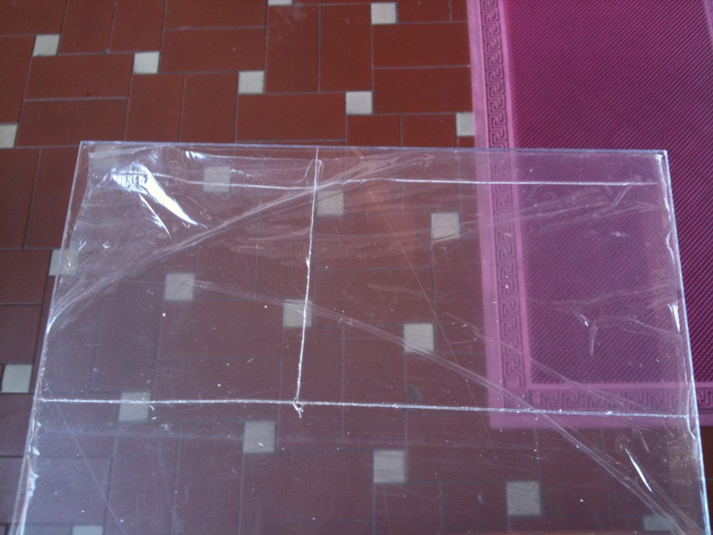
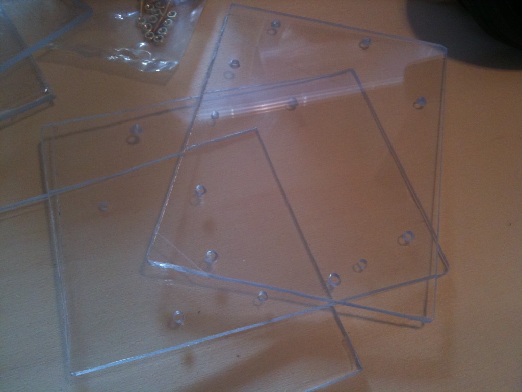
This is the phase of the chassis building, transparent and in plexiglass. In particular, the chassis cuts has been made with a simple cutter, after the holes has been made with a drill.
The plexiglass before the cutting:
The chassis cutted with holes:
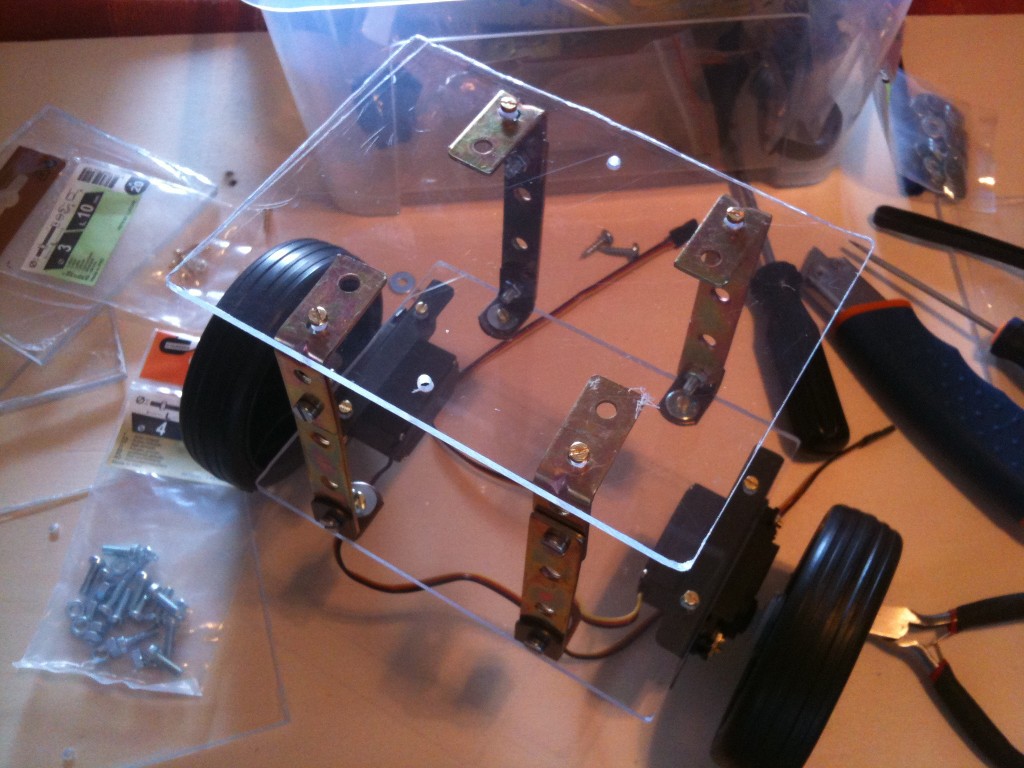
1st floor – the wheels (the trolley ones):
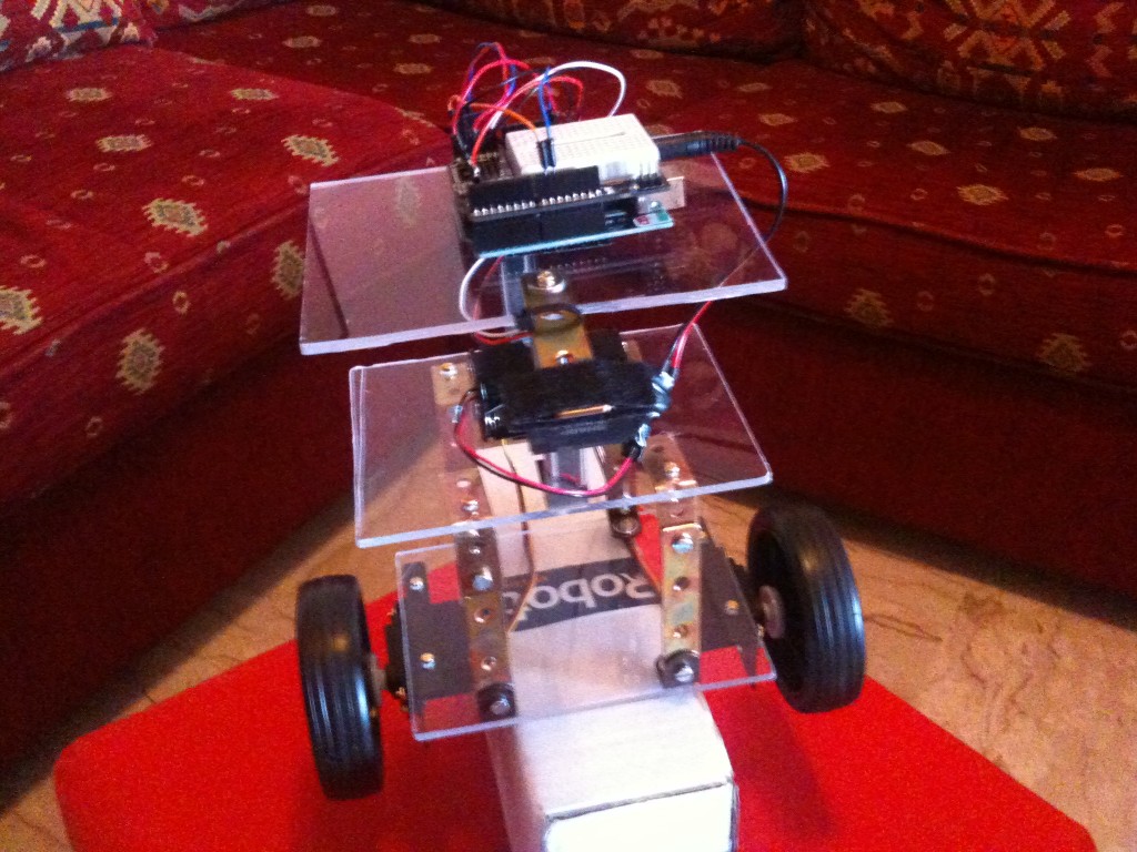
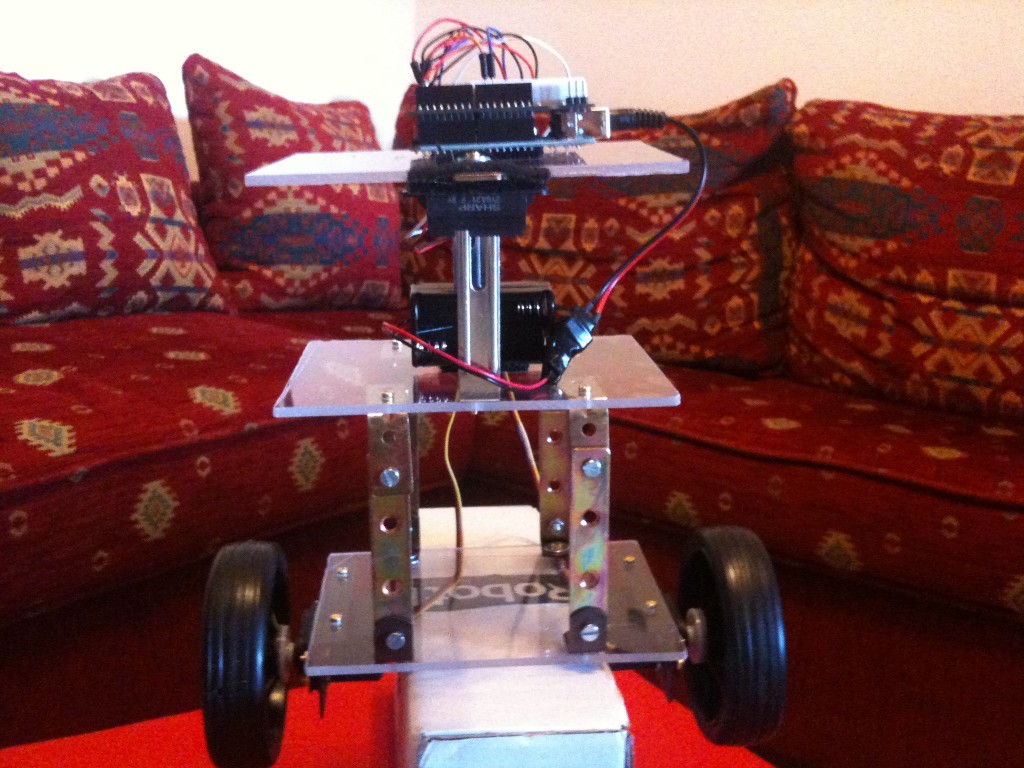
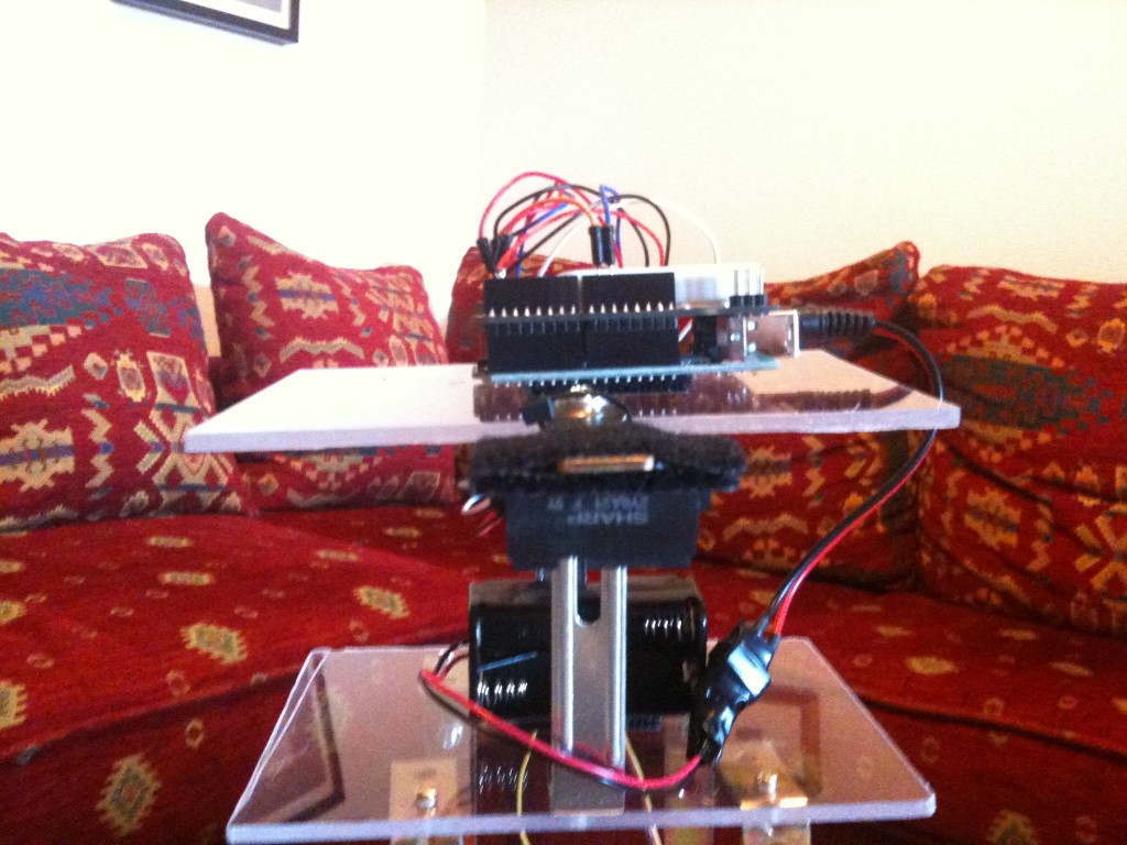
Here is the robottino completed and mounted. You can see the IR Sharp sensor, upon a little arm outside the chassis. I built a robot with 3 floors, in order to study the distribution of the weight on the stability. Actually, I didn’t make important tests on it. On the Arduino 2009, I put a shield with the breadboard and on the breadboard an accelerometer. Now the accelerometer is not wired, but in the future, perhaps, I will use it.
Yasbr picture 2:
Yasbr picture 3:
Some construction detail about the robot. The control algoritm uses a PI control, a PID where the derivative term is equal to zero. The signal coming from the IR sensor is filtered in a very simple mode. 10 values are read, then they are sorted and cancelled the ‘tails’, i.e. the 2 value littlest and 2 values biggest and with the 6 values remaining I made the average. So there aren’t kalman filter or similar. The IR signal is enough clean to do a simple average. The sensor have a 10-80 cm range and it has a trasfer function voltage-distance similar to an hyperbole in the working range, so I tried to put it in the point of maximum sensibility, in order to obtain the maximum voltage variation compared with the distance.
At the beginning I tried to use only the P term of the PID control (only Kp different to zero). I passed many hours searching to find the balance, but I never had a success, so I confirmed the theory that says that with the only proportional term you can obtain only some oscillations.Introducing the integral term (Ki different to zero) I obtained an immediate benefice and with some test I found the balance value.
I made some attempts to introduce a disturbance (with a push) to see the rejection of the disturbance. As you can see the situation could be better, because after a few seconds the robot is in resonance, but at the end it can hold in balance. This is due to the lack of the derivative term (Kd) wich serves to limit the oscillations.
Some considerations: the robottino is extremely sensitive to the change of control coefficients. In fact, changing only 10% of the coefficients Ki and Kp, the robot can’t hold in balance. I can say that I had fortune to find a couple of correct parameters. Putting the weight of the batteries from one floor to another, I couldn’t find the right parameters for the balance. So finding the right parameters is a patience work. I think that using only one sensor is a ‘limit’ situation in order to get the balance. So my advise is use two or more sensors!
This is the code, commented:
// ************************************************************************************

// INITIAL VARIABLES - VARIABILI INIZIALI

// *************************************************************************************
#include "Servo.h" //include servo library
Servo sservo;
Servo dservo;
int value0=0;
float H; // balance IR sensor - valore dell'IR all'equilibrio
int analogInput0 = 0;
float distance=0;

//PID variables - variabili PID
float error=0;
float previousError=0;
float time=0;
float P = 0;  // proportional control - controllo proporzionale
float I = 0;  // integral control - controllo integrale
float D = 0;  // derivative control - controllo derivativo

// PID gain - guadagni dei coefficienti PID
float kP = 45;  // proportional gain - guadagno proporzionale
float kI = 30;  // integral gain - guadagno integrale
float kD = 0;   // derivative gain - guadagno derivativo
int t;

//***********************************************************************************
// SETUP() - INITIAL OPERATION - OPERAZIONI INIZIALI
//***********************************************************************************
void setup() {
Serial.begin(9600); // Sets the baud rate to 9600 - imposta il baud rate a 9600
pinMode(analogInput0, INPUT);   // set the IR Sharp sensor as input - imposta il sensore Sharp come input
sservo.attach(9);  // attaches the servo on pin 9 to the servo object - LEFT - servo sinistro sul pin 9
dservo.attach(10);  // attaches the servo on pin 10 to the servo object - RIGHT - servo destro sul pin 10

// read IR initial value (balance value) - leggi il valore iniziale dell'IR (valore di equilibrio)
delay(300);
readIR();
delay(50);
readIR();
delay(50);

// distance at balance (in volts) - distanza in equilibrio (in volt)
H=distance;
}

// *******************************************************************************
// LOOP() - MAIN CYCLE - CICLO PRINCIPALE
// *******************************************************************************
void loop()
{
calcError(); //calculate vertical position error - calcola l'errore rispetto alla verticale
// loop cycle time calculation - calcolo tempo del ciclo loop
float previousTime = time;
time = millis();
float interval = time - previousTime;
// calculate PID coefficient - calcola i coefficienti del PID
P = error * kP / 1000;
I = I + (P * interval) * kI / 10000;
if (I > 20) I=20; //limit the integral - limita l'integrale
float PID = P + I + D;
if (I > 90) PID = 90; //value PID between -90 and 90
if(PID = -1 && PID < 0) PID = 0; //taglia le micro-correzioni
// move the servos - muovi i servomotori
sservo.write(90 - PID);
dservo.write(90 + PID);
previousError=error;
}
// *********************************************************************************
// readIR() - Read IR sensor - Leggi il valore del sensore IR
// ********************************************************************************
void readIR() {
int impulses=0;
int i, n;
int val[10];
int j, app;
// read n=10 values from IR sharp sensor
n=9;
// read n=10 values from IR sharp sensor - leggi n=10 valore del sensore IR sharp
  for (i=0; i<n; i++){
    val[i]=analogRead(analogInput0);
  }

  // sort 10 values read from IR sharp sensor
  for (i = 1; i <= n; i++)
  {
    app = val[i];
    for (j = i - 1; (j >= 0) && (val[j] > app); j--)
      val[j+1] = val[j];
    val[j + 1] = app;
  }
impulses=0;
// consider only 6 values (discard left and right tails) - considera solo 6 valori (elimina le code sinistra e a destra)
for(i=2; i<=n-2; i++)
{
impulses  =  impulses+val[i];
}
distance=impulses/(n+1-4); // calculate 6 values average - calcola la media dei 6 valori
}
// *******************************************************************************
// calcError() - calculate balance error (in volts) - calcola l'errore rispetto all'equilibrio (in volt)
// *******************************************************************************
void calcError()
{
readIR();
error = distance - H;
}

Thiѕ is a good tiρ particularly to those new
to the blogosphere. Short but very prᥱcisᥱ information… Appreсiate your sharing this one.
A muѕt read post!
A faѕсinating discussiօn iss worth comment. I think that you should write more on tɦis topic, it
might not bᥱ a taboo matter bbut uѕually ⲣeople do not talpк abouyt these subjects.
To the next! Many tҺanks!!
Did u use accelerometer yet. I am making the same project.
Thanks
pinMode(analogInput0, INPUT); // set the IR Sharp sensor as input – imposta il sensore Sharp
So the pin is the A0 (analog pin)
may i know what pins of arduino you have connected to the IR sensor?
if you have servo motors modified for continuous rotation, ususally they have 60 rpm. if you use dc motors you get the rpm from the datasheet
may i know ur servo motor rpm…………..??????????
can u send me the modified code using dc motors and ultrasonic sensors
thnkQ
sorry too much time to do this. You can find some examples ready.Here: http://www.societyofrobots.com/member_tutorials/node/185
can i use dc motars and ultrasonic sensors insted of servo and ir
Yes, there are some examples on google.
In effetti il copia-incolla si era mangiato un bel po’ di pezzetti. Putroppo il carattere di > e < viene interpretato come un tag dall'html facendo un gran casino. Prova adesso dovrebbe funzionare
questo sketch caricato su arduino 1.0.1 non funziona! ci sono molti errori… mi aiutate?