When I saw the “Mr. General” robot by oddbot (link), I loved it. I thought it is “expressive”, a skill difficult to find in a robot built at home. So I built my version of Mr.General with Arduino.
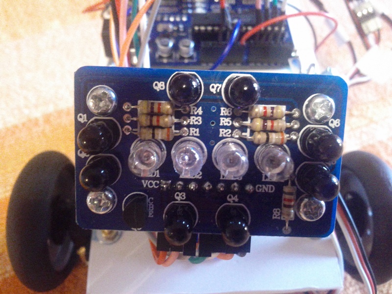
The robot is based on compound-eye sensor (link): an infrared sensor that, with a minimum of programming, knows if the object, moving ahead, is going up, down, right or left.
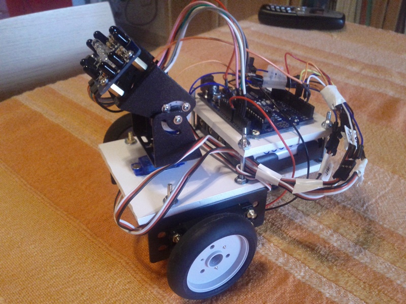
Here’s the robot:
For the building, in addition to the compound eye sensor, I used two brackets with two servo motors that allow the pan and tilt mouvement, like a head. Also these have been provided by the Dagu, that created the compound eye (link). Both these items are very cheap: the compound eye costs $ 9, pan and tilt costs 14.5 dollars, including the two servomotors.
The advantage of using pan and tilt sensor of the same company is easily understandable. They are perfectly integrated and perfectly complementing.
To complete the robot, in addition to the Arduino, I used two continuous rotation servos, a little wheel caster and two battery packs, one for the Arduino and one for the servo motors (I recommend always using separate power supplies with a common ground). The chassis is built using a PVC foam sheet of 5 mm which has an incredible ease of modeling (you cut it with a knife) and an acceptable mechanical strength and rigidity.
What the robot does? It is a diffident robot. It waits until an an object is in front. Then it starts, follows the object moving in front of him, looking like a good robot, trying to keep the right distance from the object. if the object goes too close, the robot runs away, when if the object goes away, the robot begins to chase.
Here the robot in action:
For the code, I modified the code made by Oddbot (here). This is my code:
#include <Servo.h>

#define IRleft 1 // Compound Eye Left - analog input A1
#define IRright 3 // Compound Eye Right - analog input A3
#define IRup 0 // Compound Eye Up - analog input A0
#define IRdown 2 // Compound Eye Down - analog input A2
#define IRleds 2 // Compound Eye LEDs - digital output D2

#define panPin 3 // PAN Servo - digital output D3
#define tiltPin 5 // TILt Servo - digital output D5
#define sServoPin 9 // Left Motor Servo - digital output D9
#define dServoPin 6 // Right Motor Servo - digital output D6

// definisci le costanti - define constants
byte LRscalefactor=10;  //fattore di scala - calibrare sui propri servi - calibrate depending on servo
byte UDscalefactor=10;  //fattore di scala - calibrare sui propri motori - calibrate depending on servo
// distanza minima per far muovere la testa - minimum distance to move the head
int distancemax=250;    //valore da trovare sperimentalmente - experimental value - adc value for analaog input for mimu
// distanza che provoca uno spostamento dei servi desto e sinistro - distance for moving the servos left and right
int bestdistance=450;   // valore da trovare sperimentalmente - experimental value - acd
int PanZero=78;         // stop servo di pan (destra - sinistra) - pan servo stop
int TiltZero=70;         //stop servo alto basso - tilt servo stop
int sMotorStop=90;       // stop servo sinistro - stop left servo
int dMotorStop=90;       // stop servo destro - stop right servo
int LRmax=170;           // max valore servo pan - pan servo max value
int LRmin=10;            // min valore servo pan - pan servo min value
int UDmax=170;           // max valore servo tilt - tilt servo max value
int UDmin=10;            // min valore servo tilt - tilt servo min value

// Definisci le variabili di appoggio - define global variables
int pan=PanZero;
int tilt=TiltZero;
int panscale;
int tiltscale;
int sSpeed=sMotorStop;
int dSpeed=dMotorStop;
int panOld;
int tiltOld;
int distance;
int temp;

// IR Sensors - sensori IR
int updown;
int leftright;
int leftIRvalue;
int rightIRvalue;
int upIRvalue;
int downIRvalue;

//Servomotors - Servomotori
Servo sMotor;
Servo dMotor;
Servo panLR;
Servo tiltUD;

void setup()
{
  // inizializza i servo e configura i pin
  // initialize servos and configure pins
  sMotor.attach(sServoPin);
  sMotor.write(sMotorStop);
  dMotor.attach(dServoPin);
  dMotor.write(dMotorStop);
  panLR.attach(panPin);
  panLR.write(PanZero);
  tiltUD.attach(tiltPin);
  tiltUD.write(TiltZero);

  pinMode (IRleds,OUTPUT);
}

void loop()
{
  // imposta velocità servi - speed servos set
  sMotor.write(sSpeed);
  dMotor.write(dSpeed);
  panLR.write(pan);
  tiltUD.write(tilt);

  IReye();   // leggi valori compound eye - read compound eye values
  IRfollow(); // imposta inseguimento - following set
}

void IReye()//===============================================================Read IR compound eye================================================
{
  digitalWrite(IRleds,HIGH);                                  // turn on IR LEDs to read TOTAL IR LIGHT (ambient + reflected) - attiva sensore IR (ambiente + riflessione)
  delay(5);                                                   // Allow time for phototransistors to respond - aspetta per permettere la risposta dei fototransistors
  leftIRvalue=analogRead(IRleft);                             // TOTAL IR = AMBIENT IR + LED IR REFLECTED FROM OBJECT
  rightIRvalue=analogRead(IRright);                           // TOTAL IR = AMBIENT IR + LED IR REFLECTED FROM OBJECT
  upIRvalue=analogRead(IRup);                                 // TOTAL IR = AMBIENT IR + LED IR REFLECTED FROM OBJECT
  downIRvalue=analogRead(IRdown);                             // TOTAL IR = AMBIENT IR + LED IR REFLECTED FROM OBJECT
  delay(2);
  digitalWrite(IRleds,LOW);                                   // turn off IR LEDs to read AMBIENT IR LIGHT (IR from indoor lighting and sunlight)- spegni IR per leggere luminosità ambientale (luce interna + sole)
  delay(5);                                                   // Allow time for phototransistors to respond- aspetta per permettere la rispsta dei fototransistors
  leftIRvalue=leftIRvalue-analogRead(IRleft);                 // REFLECTED IR = TOTAL IR - AMBIENT IR
  rightIRvalue=rightIRvalue-analogRead(IRright);              // REFLECTED IR = TOTAL IR - AMBIENT IR
  upIRvalue=upIRvalue-analogRead(IRup);                       // REFLECTED IR = TOTAL IR - AMBIENT IR
  downIRvalue=downIRvalue-analogRead(IRdown);                 // REFLECTED IR = TOTAL IR - AMBIENT IR

  distance=(leftIRvalue+rightIRvalue+upIRvalue+downIRvalue)/4;// distance of object is average of reflected IR - la distanza dell'oggetto è la media di quanto riflesso dal sensore IR
}

void IRfollow ()//==============================================Track object in range================================================================
{
  // ferma servi - stop servos
  sSpeed=sMotorStop;
  dSpeed=dMotorStop;

   // se il valore restituito è basso, significa che non ci sono oggetto vicini
   // if the value read is low, there aren't object in front of the sensor
    if (distance<distancemax)
  {
    // riporta il sensore in posizione di riposo - reset the sensor at zero position
    if (pan>PanZero)pan=pan-1;
    if (pan<PanZero)pan=pan+1;
    if (tilt>TiltZero)tilt=tilt-1;
    if (tilt<TiltZero)tilt=tilt+1;

  }
  else
  {
    //-------------------------------------------------------------Track object with head------------------------------------------------
    panscale=(leftIRvalue+rightIRvalue)*LRscalefactor/10; //fattore di scala - scale value
    tiltscale=(upIRvalue+downIRvalue)*UDscalefactor/10; // fattore di scala - scale value

    // se sinistra gira a sinistra la testa - if left, turn left the head
    if (leftIRvalue>rightIRvalue)
    {
      leftright=(leftIRvalue-rightIRvalue)*15/panscale;
      pan=pan-leftright;
    }
    // se destra gira a destra la testa - if right, turn right the head
    if (leftIRvalue<rightIRvalue)
    {
      leftright=(rightIRvalue-leftIRvalue)*15/panscale;
      pan=pan+leftright;
    }

    // se alto, gira in alto la testa - if up, turn up the head
    if (upIRvalue>downIRvalue)
    {
      updown=(upIRvalue-downIRvalue)*15/tiltscale;
      tilt=tilt+updown;
    }

    // se basso, gira in basso la testa - if up, turn up the head
    if (downIRvalue>upIRvalue)
    {
      updown=(downIRvalue-upIRvalue)*15/tiltscale;
      tilt=tilt-updown;
    }

    panOld=pan;
    tiltOld=tilt;
    if (pan<LRmin) pan=LRmin;
    if (pan>LRmax) pan=LRmax;
    if (tilt<UDmin)tilt=UDmin;
    if (tilt>UDmax)tilt=UDmax;

    //-------------------------------------------------------------Turn body to follow object--------------------------------------------
    // se la testa si gira più di 60 gradi, gira anche il corpo - if the head turn more than 60 degrees, turn the body
    temp=LRmax-panOld;
    if (temp<60)
    {
      sSpeed=sMotorStop-50+temp/2;
      dSpeed=dMotorStop-50+temp/2;
    }
    temp=panOld-LRmin;
    if (temp<60)
    {
      dSpeed=dMotorStop+50-temp/2;
      sSpeed=sMotorStop+50-temp/2;
    }

    //------------------------------------------------------Move forward or backward to follow object------------------------------------
    // se l'oggetto è a distanza inferiore a quella bestdistance, muovi per tornare a quella distanza
    // if the object distance is less than bestdistance, move the robot to go again to the same distance
    temp=distance-bestdistance;
    temp=abs(temp);

    if (temp>10)
    {
      temp=temp-10;
      if (distance>bestdistance)
      {
        dSpeed=dSpeed-temp/3;
        sSpeed=sSpeed+temp/3;
      }
      else
      {
        dSpeed=dSpeed+temp/3;
        sSpeed=sSpeed-temp/3;
      }
    }
  }
}
