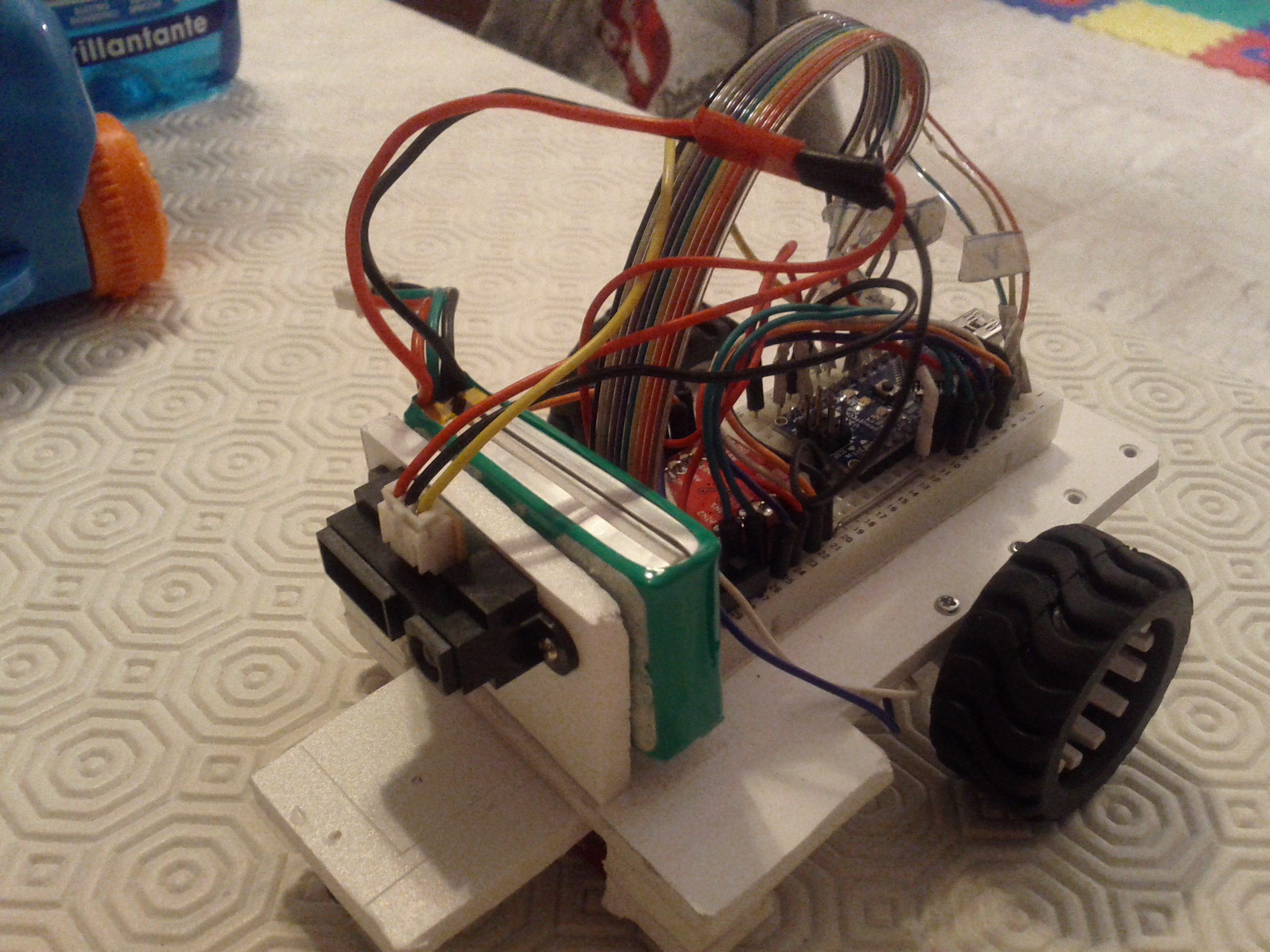
Microbo(t) – Advanced line follower Posted inRobottini Although it is one of the classics of robotics for beginners, the line follower robot, made at high level, is quite complex. On Youtube you can see line follower running at 3 m /…
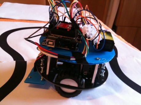
Linea – Line follower Posted inRobottini Linea is my first line follower based on Arduino. A line follower is a robot for beginners. In fact…