
I’m often thinking if it is possible to make Art with Arduino. Arduino is a machine, a little computer made with electronic circuits. It hasn’t a soul. Can an Arduino make Art? This is my question.
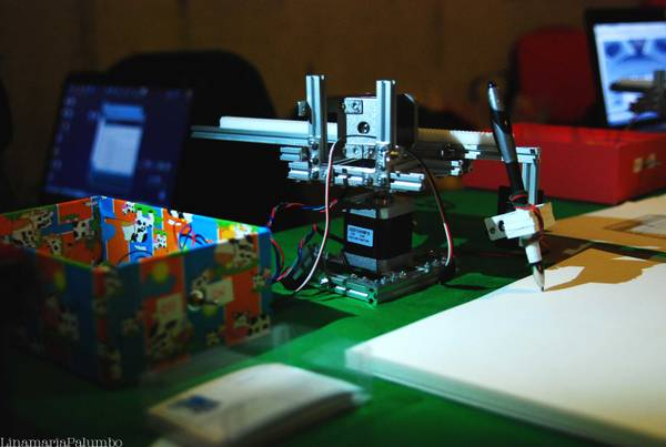
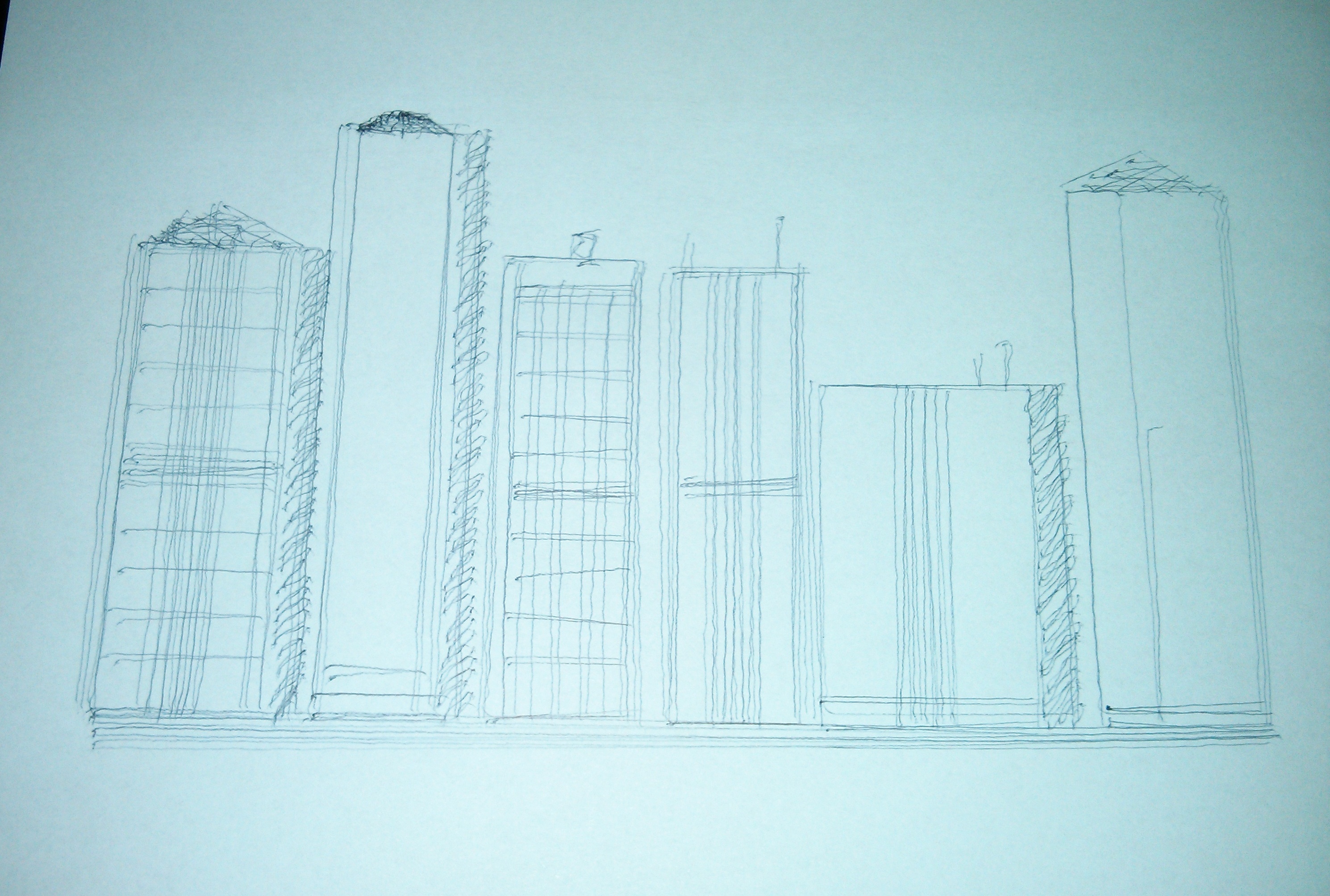
I’m trying to do something with Arduino that could be Art, or similar to Art. The Arts are painting, poetry, music, sculpture and so on. I’m trying to do something in different Arts. The road is long but I began to travel it. This is my first experiment with painting. Indeed, a easy form of painting, the sketching in Black and White. Arduino drives a robot arm, that with only a pen sketches a city skyline. The skyline is every time different, the buildings are always different. The arm tries to imitate the human sketching, with errors, shaking lines not parallel and so on. The arm tries to be human, to make a little form of Art. This is the goal, I don’t know if the goal is reached. The judgment is yours.
The robotic arms are among the most fascinating robot that you can build. There are many commercial robotic arms with 4-5-6 axes, while, at amateur level, there are no polar arms.
The arms using polar, instead of Cartesian coordinates (x and y), the polar coordinates (angle and radius).
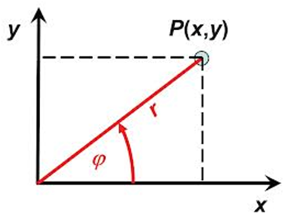
So, the point P(x,y) in polar coordinates became P(r,phi). This means a line, which in polar coordinates is described by a very simple equation, in polar coordinates becomes a complex and more difficult, because the radius can increase and decrease while describing the line.
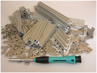
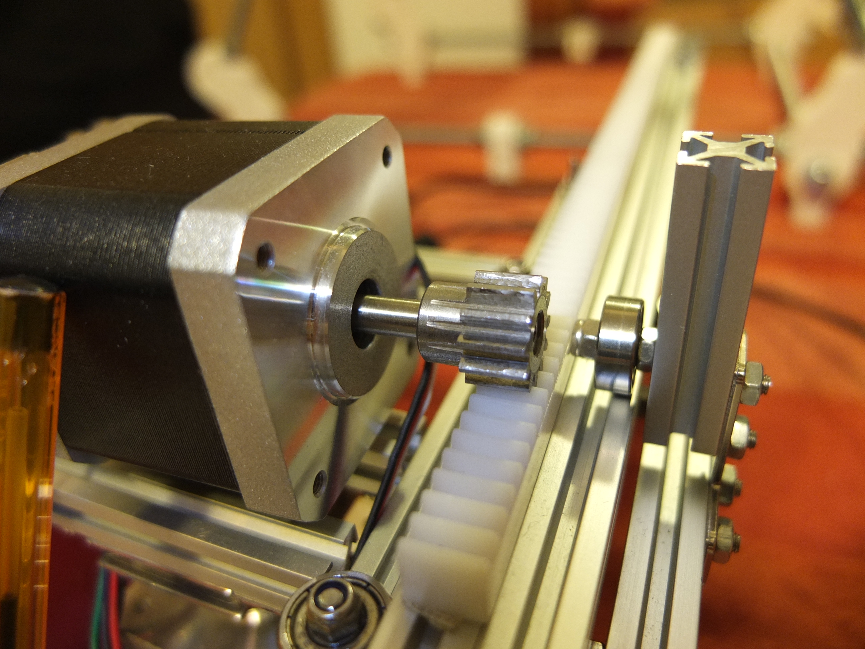
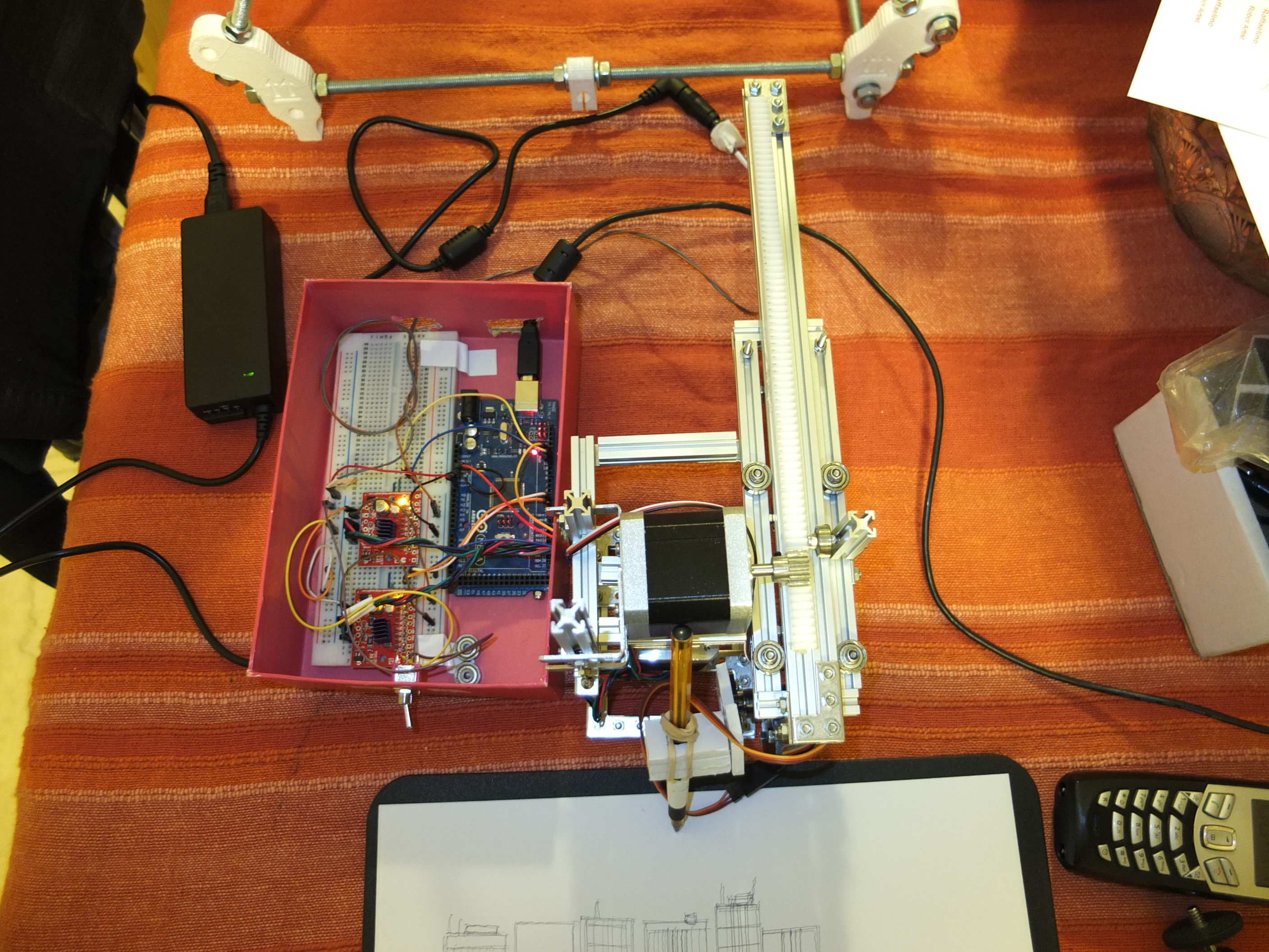
So, which is the advantage using the polar coordinates? The advantage is the robot is very simple to build. I used also an awesome aluminum infrastructure based on Makerbeam (www.makerbeam.eu) , that allows to build the robot similar to the Lego, with the advantage that all is in metal and not in plastic. Makerbeam is an open-sourced extruded beam construction kit. I got a kit, and this is my first project using it.
The hardware is:
– 1 arduino (2009/uno or Mega)
– a kit of makerbeam for the chassis and 16 ball bearings (www.makerbeam.eu)
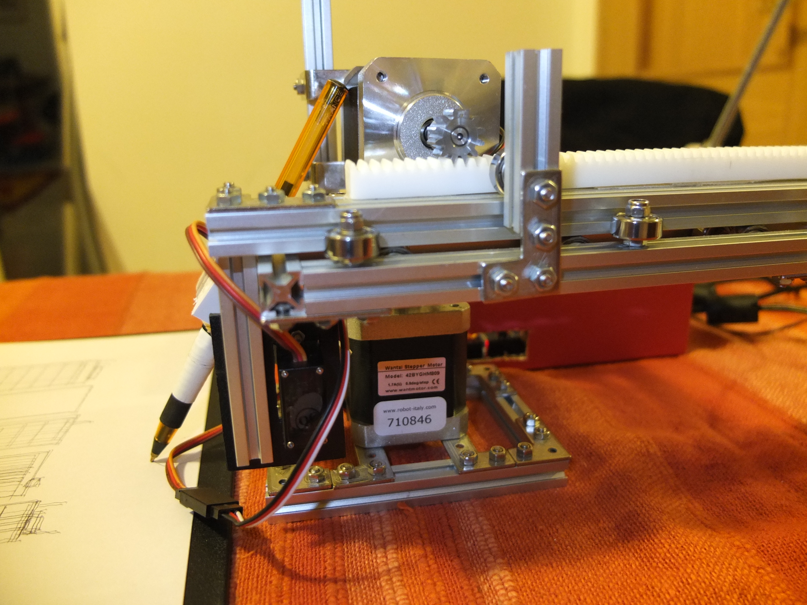
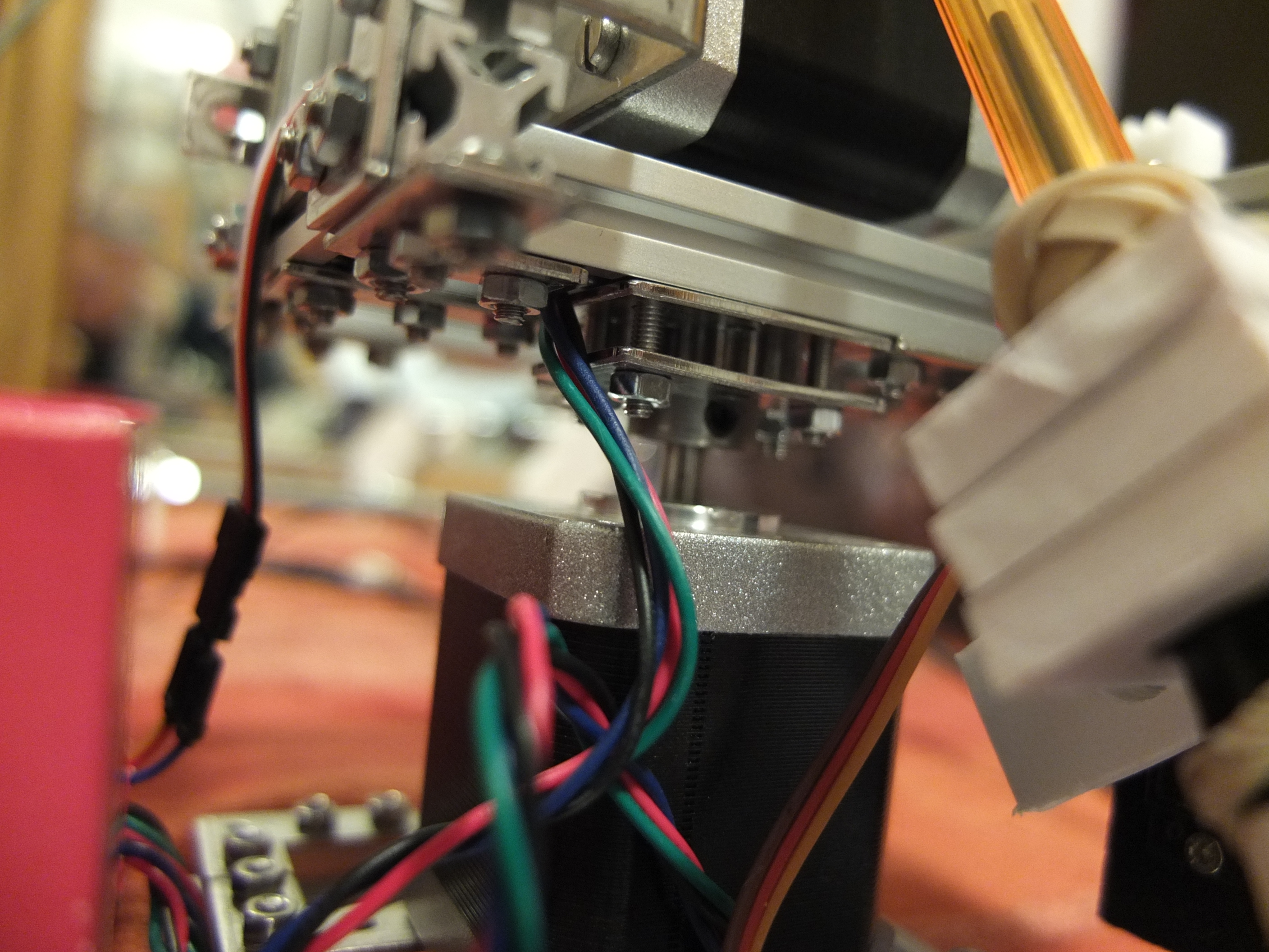
– 2 stepper nema 17 400 steps, 0.9° (www.robot-italy.com)
– 2 big easy stepper driver (www.robot-italy.com)
– 2 pignons and 1 gear rack (www.conrad.com)
– 1 little servo motor (www.robot-italy.com)
– 1 pen
This is the robot:
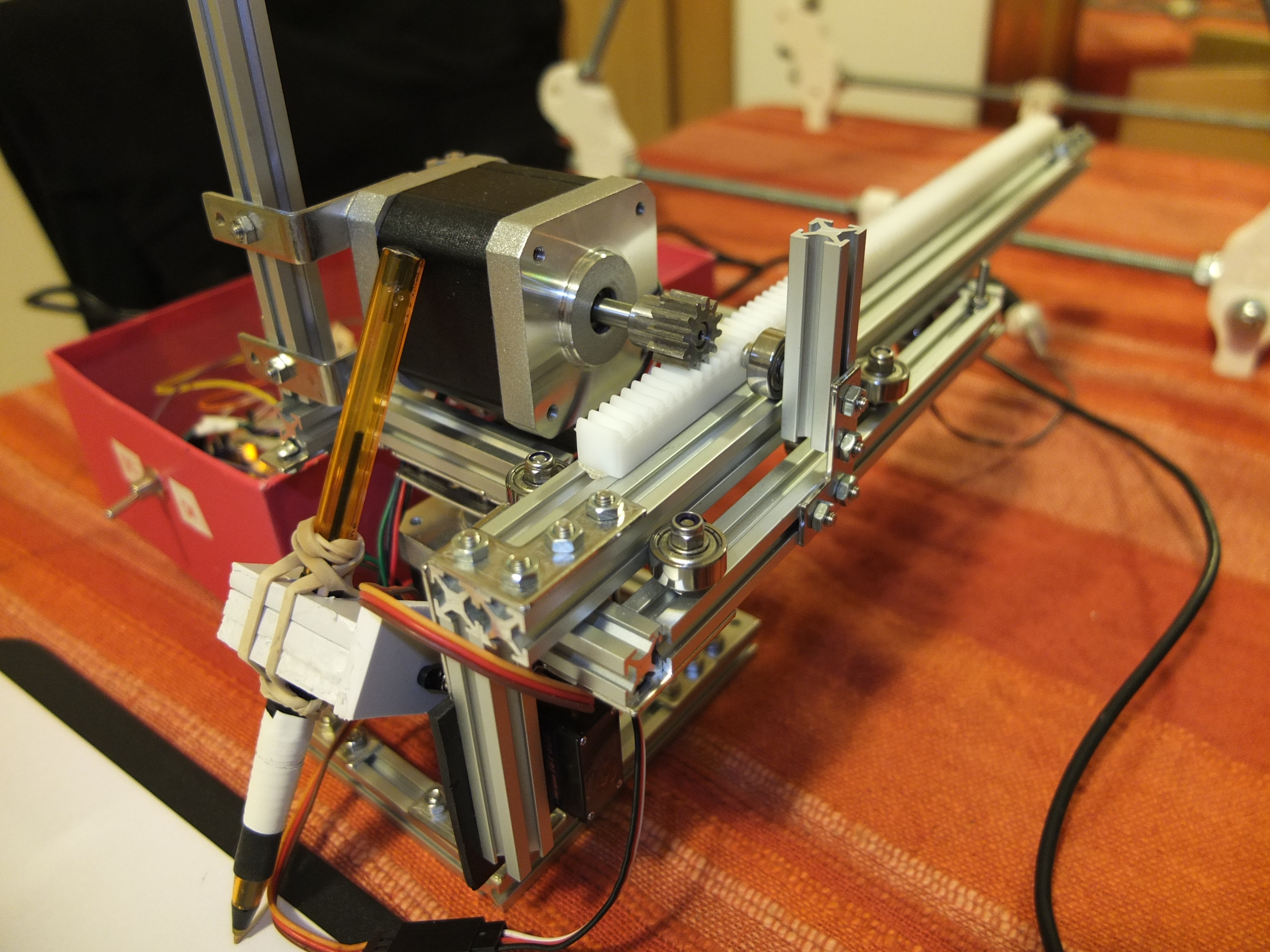
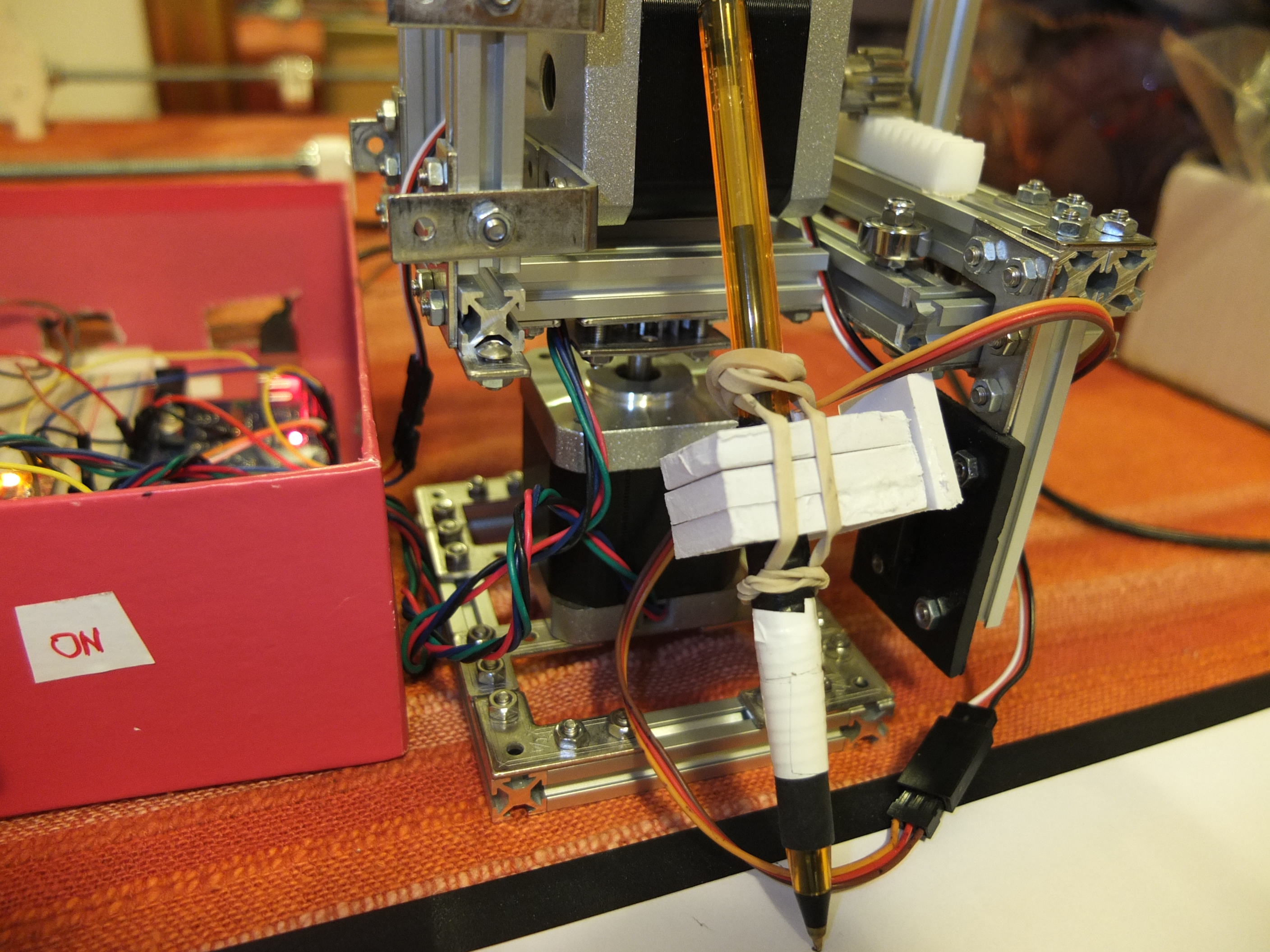
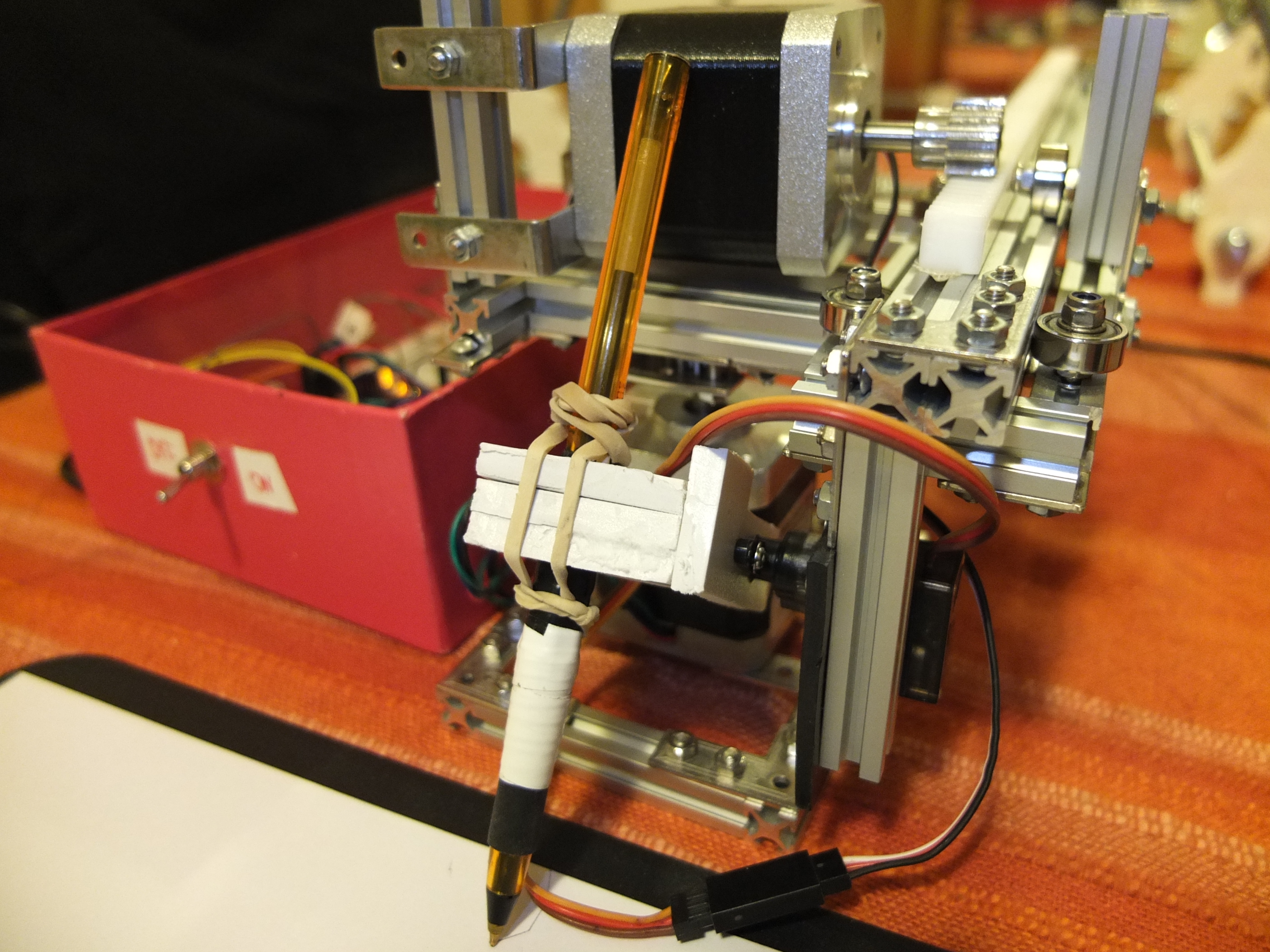
The robot has 2 dof: radius and angle. The forward and inverse kinematics are simple.
The only two shapes that are possible to draw when running one motor at a time is a radial line or a circle segment. The Arduino program implements sort of the Bresenham’s line drawing algorithm to draw segments. Each segment is divided into small segments (steps). Then, for each step we translate this movement to its corresponding changes in the polar coordinate system, angle and radius. This is finally translated to the number of steps to run each motor.
The robot can have a good precision: the balance is between good speed and good precision. If the robot has a low speed it can be very very precise. When the speed grow the precision goes down. But in this work the precision is not very important. The goal is to imitate a human sketch, and the human when are sketching are not precise.
For the sketch algorithm I’m inspired by this processing sketch: http://www.openprocessing.org/sketch/12095 semplified for Arduino. The robot can work alone, without a computer, all the logic is inside the Arduino.
The main inspiration for the polar arm robot building and for the motor driving software comes from this awesome robot: http://roxen.github.io/polar-plotter/
You can see the robot in action here:
https://www.youtube.com/watch?v=gHZ8i3iptas
The code used for the robot is available here: citta_disegna
Send me a arduino programming code for this project….
Hardware is the tough job for Diyers like me, is it possible to customise this project for Microwave stove? I want to use stepper motor to replace the microwave rotary motor, and add a beam across over the spinning plate.
Do you have a scheme or something for the building of the backbone?
hello, I can not compile the polar .ino plotter
you can help? Some
C:\Users\Bruno\Desktop\arduino-1.6.5-r2\hardware\tools\avr/bin/avr-g++ -c -g -Os -w -fno-exceptions -ffunction-sections -fdata-sections -fno-threadsafe-statics -MMD -mmcu=atmega2560 -DF_CPU=16000000L -DARDUINO=10605 -DARDUINO_AVR_MEGA2560 -DARDUINO_ARCH_AVR -IC:\Users\Bruno\Desktop\arduino-1.6.5-r2\hardware\arduino\avr\cores\arduino -IC:\Users\Bruno\Desktop\arduino-1.6.5-r2\hardware\arduino\avr\variants\mega -IC:\Users\Bruno\Desktop\arduino-1.6.5-r2\libraries\Servo\src C:\Users\Bruno\AppData\Local\Temp\build6718834568614015174.tmp\plotter_polar.cpp -o C:\Users\Bruno\AppData\Local\Temp\build6718834568614015174.tmp\plotter_polar.cpp.o
In file included from plotter_polar.ino:1:0:
plotter_polar.ino:8:22: error: variable ‘char_0’ must be const in order to be put into read-only section by means of ‘__attribute__((progmem))’
plotter_polar.ino:9:22: error: variable ‘char_1’ must be const in order to be put into read-only section by means of ‘__attribute__((progmem))’
plotter_polar.ino:105:26: error: variable ‘chars’ must be const in order to be put into read-only section by means of ‘__attribute__((progmem))’
plotter_polar.ino: In function ‘void loadChar(char)’:
plotter_polar.ino:522:26: error: ‘prog_void’ was not declared in this scope
plotter_polar.ino:522:36: error: expected primary-expression before ‘)’ token
plotter_polar.ino:528:36: error: expected primary-expression before ‘)’ token
variable ‘char_0’ must be const in order to be put into read-only section by means of ‘__attribute__((progmem))’
thanks
Awesome project !
I have done the same robot as yours but with the difference that I have to use DC motors (for the rotatory and linear movement). Could you give me a hint on how to control them ? The objective is to be able to draw geometric figures.
The motors movement calculation have to be accurate. So you have to use the encoders. Sorry but never done by me, so I can’t help you
I am currently an engineering student I have to do a prismatic rotary robot
Very nice project.
I have really appreciated your photos/explanation.
Please could you share with me your source code ?
My email : [email protected]
Many thanks regards.
I read your Circuit Cellar article today and I’m interested in the face drawing system you mentioned. I did something similar a few years ago (http://www.instructables.com/id/Scratch-2/), and I’d love to swap notes – I’m especially interested in how you convert a raster format pseudo-line drawing into vector paths for actual drawing with a pencil.
Could I see the code you mentioned in the article please? The code I used is at http://www.gtoal.com/cld/ and is directly derived from http://www.cs.umsl.edu/~kang/Papers/kang_npar07.html – there’s a C and a C++ version in the directory on my server.
I haven’t done much with that project for a couple of years, but this year I built a CNC Etch-a-Sketch, and I wouldn’t mind resurrecting the project for that hardware… ( http://www.instructables.com/id/Etch-a-Sketch-LOGO-EASiLOGO/ )
Regards
Graham
I send you the source code. Check your email 🙂