Archive for category Robottini

Simple talking robot

 Giving the voice to a toy always has been a dream when I was a child. There weren’t talking toys and the dream was destinated to stay a dream. With the power of the modern microcontrollers, like Arduino, to have a talking robot is one of the things that always I desidered to do. You can build a talking robot in two ways:

  • with the tex-to-speech, writing a text that the robot says
  • recording some audio files with inside the voice already recorded that the robot repeats

The text-to-speech is the best way to do a robot talking. You write a text, and he reads the text: this is the fastest way, but you need a chip that implements the text-to-speech. It is easy if your language is English, not easy if your language is different. For me, the language is the Italian and I haven’t found any cheap chip for italian text-to-speech.

So I used the second method, recording the voice. The method is more complex, but at the end the result is the same.
I built a simple robot, that can be made by every beginner, that does 2 things:

  • it goes around, avoiding obstacles with an ultrasound sensor
  • it talks, thanks to an audio chip

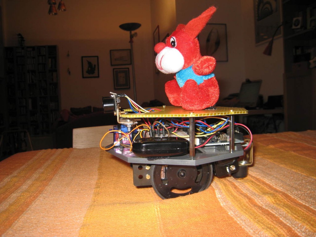
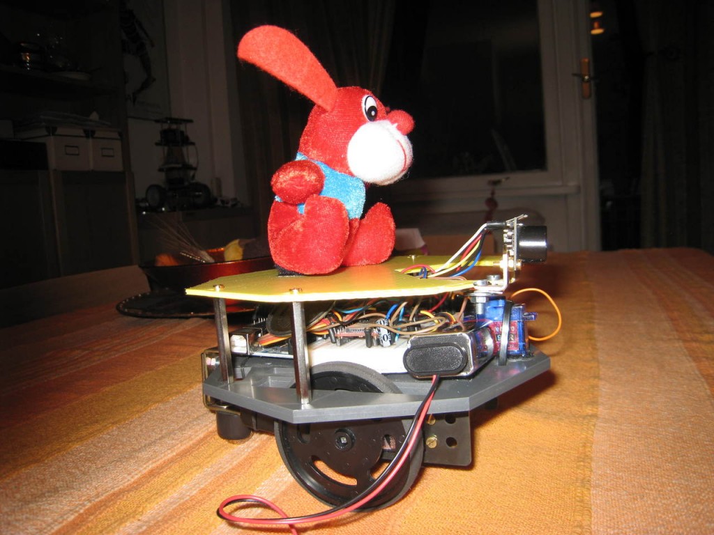
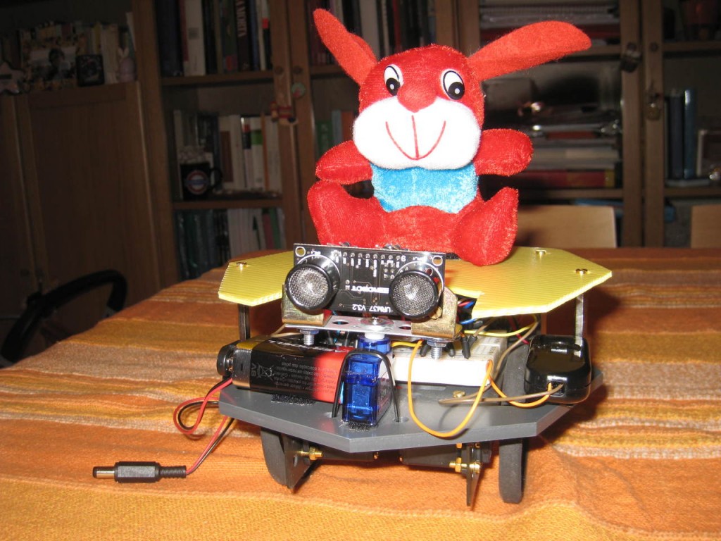
The robot is basically a toy, that fascinates my son, a little child of few months old. He enjoys to see the robot turn around, talking with robotic voice. I did it just for that. Let me to introduce Geronimo 2, the little talking robot:

Geronimo in action:

The little robot is based on two projects already presented in the past: this and this. In these links you can find some details on the building and the hardware. It uses a DFRobot URM37 Ultrasound sensor and a SOMO-14D audio chip, used to talk. This audio chip is low cost (20 euros) and it works with few components (only one 220uf capacitor) and it can be set with an Arduino.
The SOMO-14D plays only files codified with a proprietary format (AD4). But it is available a practical sw that converts MP3 in AD4 format.
In order to allows to talk to the robot, I used a software for italian speech(called Er Finestra), but you can use the speech software you want. For almost all the languages a similar little utility is available.
One problem resolved is due to the fact that Er Finestra can only say something. It can’t at the same time to say and to record. So I downloaded Audacity, an editor audio free, that can record every sound that pass in the sound card.
So you have to start Er Finestra and at the same time to start Audacity that records the phrases read by Er Finestra. Then you can convert the Phrase from MP3 to AD4. The process could be seem complex, but it is more difficult to say than to do.
I read with Er Finestra 40 pieces, I converted them and the robot can say them randomly.
It is possible to use an intelligent algorithm in order to say something responding to external stimulus. For example, to say ‘turn right’, ‘turn left’ or something of similar. The audio chip can play also musical pieces, songs, so it is possible to see the robot going around singing !

The code used for Arduino is simple and it is organized in two parts:
– one for the robot navigation
– one for audio playing
The code is commented, so I don’t think you will have comprehension problems:

//Semplice robot autonomo con sensore ad ultrasuoni per evitare gli ostacoli e chip audio per parlare o suonare una canzone.
//Simple autonomous robot with ultrasonic sensor for obstacles avoidance and audio player chip. It can speak or play a song. 
// written by alegiaco
// Creative Commons Attribution-NonCommercial-ShareAlike 3.0 Unported License
//include URM Library - Includi la libreria URM
#include "URMSerial.h"
#include//include servo library - includi la libreria del servo
Servo sservo;
Servo dservo;
Servo uservo;
int ang=0;
int angolomax=0;
int distmax=0;
int value=100;
int ind=0;
int rotazione=0;

// Definizione delle misure per il sensore ad ultrasuoni URM37
// Measures definition for ultrasound URM37
#define DISTANCE 1
#define TEMPERATURE 2
#define ERROR 3
#define NOTREADY 4
#define TIMEOUT 5

//angolo di riposo dei servi delle ruote
// standing angle for servos
#define RIPOSOS 93
#define RIPOSOD 93

// inizializza l'oggetto della libreria urm del sensore ultrasuoni
// initialize object for urm library
URMSerial urm;

//parte relativa al SOMO-14D - Chip Audio - SOMO-14D initial variables assegnation
const unsigned int minVol= 0xfff0;    // Minimum volume - Volume minimo
const unsigned int maxVol= 0xfff7;    // Max Volume - Volume massimo
const unsigned int PlyPse = 0xfffe;   // Play or Pause
const unsigned int Stop= 0xFFFF;      // Stop
const int pinClock= 4;                // clock sul pin dell'arduino - Clock on Arduino pin
const int pinData =5;                 // data sul pin dell'arduino - Data on arduino pin
const int pinBusy =8;                 // busy sul pin dell'arduino - Byte on Arduino pin
const int pinReset=12;                // reset sul pin dell'arduino - Reset on arduino pin
unsigned int volLevel=0x0005;         // imposta massimo livello volume - volume max level
int Song;                             // current Song - canzone attuale
unsigned int vol;                     // volume
int secondi=0, ultimotempo=0;         // varibili per durata brani - variables for songs time
int brano=0;                          // brano riprodotto - song played
int durata[40]={
7,8,14,19,5,8,33,28,5,5,5,5,6,5,5,5,5,6,6,7,6,5,7,8,8,10,4,6,5,6,5,10,5,6,7,6,4,5,6,5}; // durata singoli brani - single songs time

//****************** fine variabili iniziali ************************************
//****************** end initial variables **************************************

void setup()
{
Serial.begin(9600);                          // baud rate - 9600
urm.begin(6,7,9600);                         // RX Pin, TX Pin, Baud Rate
sservo.attach(10);                           // Attacca il servo sinistro al pin 10 - servo left to pin 10
dservo.attach(9);                            // Attacca il servo destro al pin 9 - - servo right to pin 9
uservo.attach(3);                            // Attacca il servo degli ultrasuoni al pin 3 - ultrasonic sensor servo to pin 3
delay(100);
uservo.write(90);                            // metti il servo degli ultrasuoni dritto - ultrasonic servo straight

pinMode(pinData,OUTPUT);                     // set pin 4 to output for Data -
pinMode(pinClock,OUTPUT);                    // set pin 3 to output for clock
pinMode(pinReset,OUTPUT);                    // set pin 7 to allow software reset - imposta pin 7 per il sw reset
pinMode(pinBusy,INPUT);                      // set pin 6 to monitor while Song is playing - pin 6 di monitoraggio mentre il brano è suonato
Reset();                                     // resetta il somo-14D chip audio - somo-14d chip audio reset
}

void loop()
{

playSOMO14D();                                 // suona un brano con chip audio - play song with chip audio
delay(30);                                     // attendi allineamento dei servi - wait for servo alignement
sempreDritto();                                // fai andare il robot sempre dritto - always straight
getMeasurement(DISTANCE);                      // richiedi una nuova lettura della distanza - ask for new distance reading

if (value 0)                    // se il valore e' < 20 cm stiamo per sbattere - if the value is < 20 we are crashing
{
fermaServi();                                // ferma il robot mentre controlla gli ostacoli intorno - stop servos
scandisciAmbiente();                         // controlla gli ostacoli ogni 30 gradi - control obstacles every 30 degrees
ruotaServi();                                // fai girare i servi nella direzione della max strada libera - turn servos in the free direction

}
}

// ------------------ ferma i servi dei motori: robot fermo -----------------------
// ------------------ stop robot - stop servos -----------------------
void fermaServi()
{
sservo.write(RIPOSOS); // ferma ruota sinistra - stop left wheel
dservo.write(RIPOSOD); // ferma ruota destra - stop right wheel
}

// ------------------ fai andare il robot sempre dritto -----------------------
// ------------------ go straight -----------------------
void sempreDritto()
{
sservo.write(RIPOSOS + 80); // fai andare il robot dritto - go straight
dservo.write(RIPOSOD - 80); // fai andare il robot dritto - go straight
}

// ------------------ controlla gli ostacoli ogni 30 gradi -----------------------
// ------------------ control obstacles every 30 degrees -----------------------
void scandisciAmbiente()
{
angolomax=0; // imposta l'angolo di migliore uscita a zero - set exit angle to zero
distmax=0;   // imposta la distanza di uscita migliore a zero - set max distance read to zero
for (ang=0; ang<=6; ang++) // fai un ciclo per controllare dove sono gli ostacoli - cycle to control where are the obstacles
{
delay(100); //attendi allineamento servo ultrasuoni - wait for ultrasonic sensor alignment
uservo.write(ang*30); // imposta il servo degli ultrasuoni sul valore assunto da ang - set to ultrasonic sensor servo to value of ang variable
float sommadist=0;
int contavalori=0;
// 5 letture della distanza. sommale e fai la media
// read 5 time the distance, sum and average
for (int lettura=1; lettura<=5; lettura++)
{
value=-2;
getMeasurement(DISTANCE); //richiedi una nuova lettura della distanza - ask for a new distance read
delay(20);
if (value >= -1 && value < 300) // solo se la distanza è tra -1 e 300 - only if the distance is between -1 and 300
{
if (value==-1) value=1000; //-1 = infinito
sommadist = sommadist + value;
contavalori++;
}
}
int dist=sommadist/contavalori;
if (dist > distmax) // verifica che la distanza letta sia maggiore del max - distance read > max
{
angolomax=ang;  // se e' maggiore del max imposta il nuovo angolo max e - if > max, set new angle max
distmax=dist;  // la nuova distanza max - new max distance

}
}
uservo.write(90); //rimetti il servo degli ultrasuoni dritto - ultrasonic servo straight
}

// ------------------ ruota i servi nella direzione di massimo spazio libero -----------------------
// ------------------ turn servos to max free distance -----------------------
void ruotaServi()
{
for (ind=1; ind < (abs(angolomax-3))*3; ind++)
{
if (angolomax <= 3) { //tra 0 e 90 gradi. between 0 and 90 degrees
sservo.write(RIPOSOS-90);
dservo.write(RIPOSOD-90);
}
else // tra 90 e 180 gradi - between 90 and 180 degrees
{
sservo.write(RIPOSOS+90);
dservo.write(RIPOSOD+90);
}
delay (50); // attendi allineamento servi - wait for servos alignment
}
}

// ------------------ acquisisci misurazione distanza -----------------------
// ------------------ take distance -----------------------
int getMeasurement(int mode)
{
// Request a distance reading from the URM37 - richiedi distanza da URM37
switch(urm.requestMeasurementOrTimeout(mode, value)) // Find out the type of request - verifica tipo richiesta
{
case DISTANCE: // Double check the reading we recieve is of DISTANCE type - doppio check che sia una distanza
return value;
break;
case TEMPERATURE:
return value;
break;
case ERROR:
Serial.println("Error");
break;
case NOTREADY:
Serial.println("Not Ready");
break;
case TIMEOUT:
Serial.println("Timeout");
break;
}

return -2;
}


This is the SOMO-14D code part:


// ------------------ play song on SOMO-14D -----------------------
void playSOMO14D()
{
if (int(millis()/1000) > ultimotempo + durata[brano]) { //verifica se il brano precedente è terminato - verify if previous song is finished
ultimotempo=int(millis()/1000);
brano=int(random(1, 41)); // prendi un brano a caso - take random song
PlaySong(brano); // suona brano - play song

}
}

/************************************************** ********************************
Send Sequence - Invia sequenza
************************************************** ********************************/

void sendData(int ThisSong)
{
int TheSong = ThisSong;
int ClockCounter=0;
int ClockCycle=15;//0x0f;

digitalWrite(pinClock,HIGH);     // Hold (idle) for 300msec to prepare data start
delay(300);
digitalWrite(pinClock,LOW);       //Hold for 2msec to signal data start
delay(2);  //2msec delay

while(ClockCounter <= ClockCycle)
{ digitalWrite(pinClock,LOW);
if (TheSong & 0x8000)
{digitalWrite(pinData,HIGH);
}
else
{digitalWrite(pinData,LOW);
}
TheSong = TheSong << 1;
delayMicroseconds(200);      //Clock cycle period is 200 uSec - LOW
digitalWrite(pinClock,HIGH);
ClockCounter++;
delayMicroseconds(200);      //Clock cycle period is 200 uSec - HIGH
}

digitalWrite(pinData,LOW);
digitalWrite(pinClock,HIGH);    // Place clock high to signal end of data
}

/************************************************** ********************************
Plays Stored Song by Number - Suona un brano per numero del brano
************************************************** ********************************/

void PlaySong(int numero)
{ sendData(Stop);
int SongNumber=numero;
if (SongNumber >= 0 && SongNumber < 512){     // Song is within range limit
Serial.print("-> Song No.");
Serial.println(SongNumber);
sendData(SongNumber);}

}

/************************************************** ********************************
Reset SOMO
************************************************** ********************************/
void Reset()
{
//Serial.println("RESET.");
digitalWrite(pinReset,LOW);
delay(50);
digitalWrite(pinReset,HIGH);
Song=0;
}
 

YASBR – Yet Another Self-Balancing Robot

The self-balancing robot building is today an activity that every robot builder can perform with Arduino.  Searching in Google for self-balancing robot you can find tons of realizations, with tons of different sensors and control systems. So to build a self balancing robot is a standard task for the robot builder, like a simple home rover.

Trying  to be at least original, I though to build a self balancing robot with these goals:

  • low-low-cost
  • simple in the hardware
  • simple in the software

So I tried to build a self-balancing robot using only one sensor: a Sharp IR distance sensor e nothing else. No gyro, no accelerometer, no other sensors. All is self-built, in the DIY pure spirit.

These are the components used:

  • Plexiglass chassis
  • Wheels for servo (Boe-Bot wheels). At first time I tryied to use two trolley wheels, but without success
  • Servos modified
  • Sharp IR sensor 10-80 cm
  • Arduino 2009
  • 2 batteries pack 4×1,2V
  • some screws, jumpers etc.

We are under 100 euros, a good results concerning the cost.

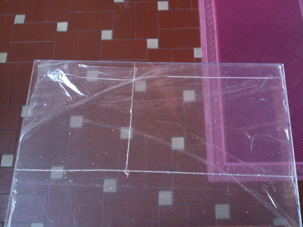
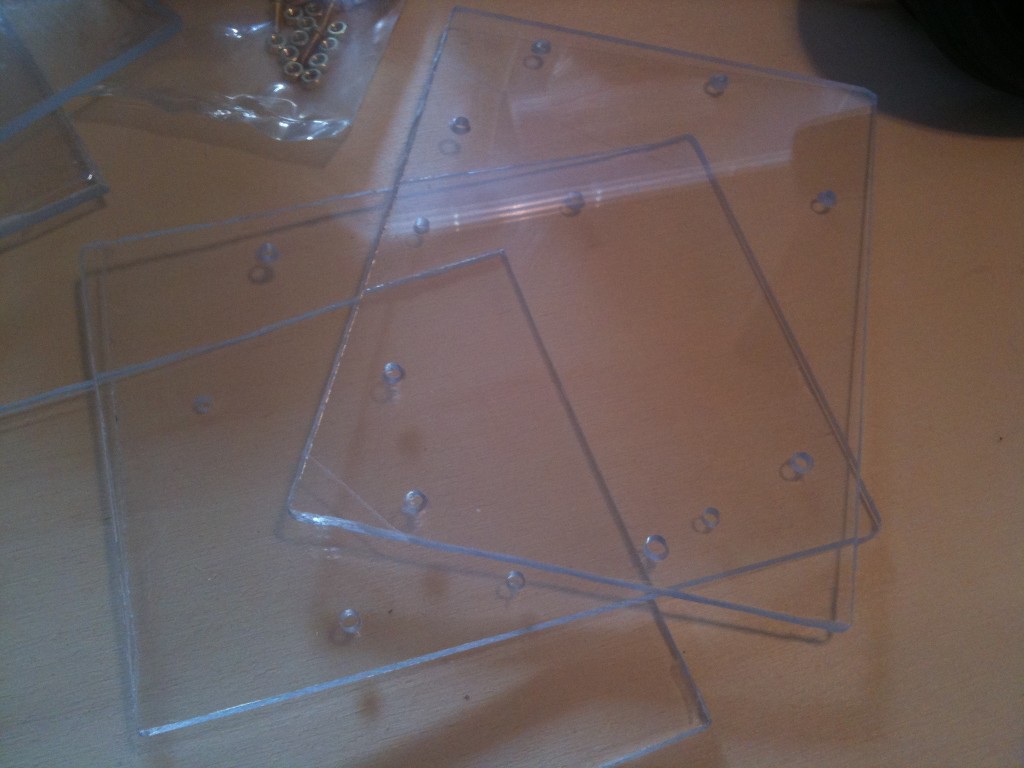
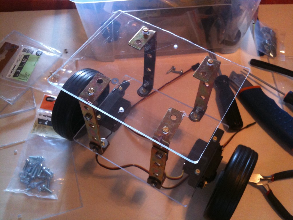
This is the phase of  the chassis  building, transparent and in plexiglass. In particular, the chassis cuts has been made with a simple cutter, after the holes has been made with a drill.

The plexiglass before the cutting:


The chassis cutted with holes:


1st floor – the wheels (the trolley ones):


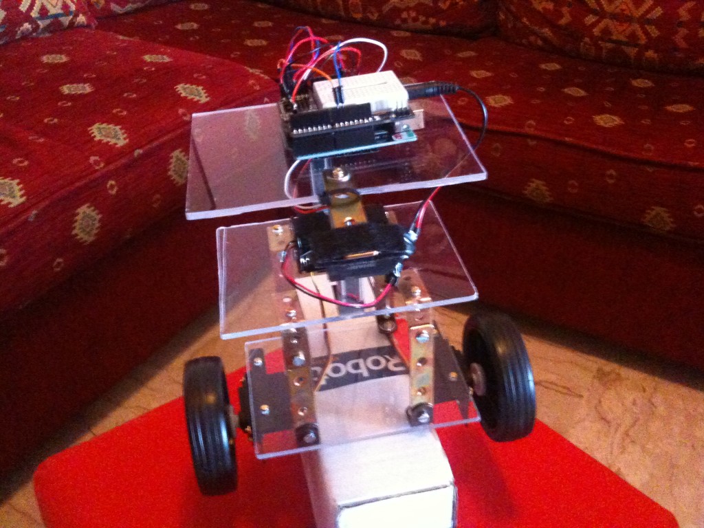
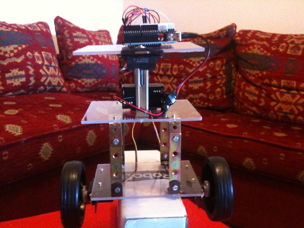
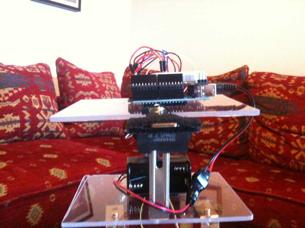
Here  is the robottino completed and mounted. You can see the IR Sharp sensor, upon a little arm outside the chassis. I built a robot with 3 floors, in order to study the distribution of the weight on the stability.  Actually, I didn’t  make important tests on it. On the Arduino 2009, I put a shield with the breadboard and on the breadboard an accelerometer. Now the accelerometer is not wired, but in the future, perhaps, I will use it.


Yasbr picture 2:


Yasbr picture 3:


Some construction detail about the robot. The control algoritm uses a PI control, a PID  where the derivative term is equal to zero. The signal coming from the IR sensor is filtered in a very simple mode. 10 values are read, then they are sorted and cancelled the ‘tails’, i.e. the 2 value littlest and 2 values biggest and with the 6 values remaining I made  the average. So there aren’t kalman filter or similar. The IR signal is enough clean to do a simple average. The sensor have a 10-80 cm range and it has a trasfer function voltage-distance similar to an hyperbole in the working range, so I tried to put it in the point of maximum sensibility, in order to obtain the maximum voltage variation compared with the distance.
At the beginning I tried to use only the P term of the PID control (only Kp different to zero). I passed many hours searching  to find the balance, but I never had a success, so I confirmed the theory that says that with the only proportional term you can obtain only some oscillations.Introducing the integral term (Ki different to zero) I obtained an immediate benefice and with some test I found the balance value.

I made some attempts to introduce a disturbance (with a push) to see the rejection of the disturbance. As you can see the situation could be better, because after a few seconds the robot is in resonance, but at the end it can hold in balance. This is due to the lack of the derivative term (Kd) wich serves to limit the oscillations.


Some considerations: the robottino is extremely sensitive to the change of control coefficients. In fact, changing only 10% of the coefficients Ki and Kp, the robot can’t hold in balance. I can say that I had fortune to find a couple of correct parameters. Putting the weight of the batteries from one floor to another, I couldn’t find the right parameters for the balance. So finding the right parameters is a patience work. I think that  using only one sensor is a ‘limit’ situation in order to get the balance. So my advise is use two or more sensors!

This is the code, commented:


// ************************************************************************************

// INITIAL VARIABLES - VARIABILI INIZIALI

// *************************************************************************************
#include "Servo.h" //include servo library
Servo sservo;
Servo dservo;
int value0=0;
float H; // balance IR sensor - valore dell'IR all'equilibrio
int analogInput0 = 0;
float distance=0;

//PID variables - variabili PID
float error=0;
float previousError=0;
float time=0;
float P = 0;  // proportional control - controllo proporzionale
float I = 0;  // integral control - controllo integrale
float D = 0;  // derivative control - controllo derivativo

// PID gain - guadagni dei coefficienti PID
float kP = 45;  // proportional gain - guadagno proporzionale
float kI = 30;  // integral gain - guadagno integrale
float kD = 0;   // derivative gain - guadagno derivativo
int t;

//***********************************************************************************
// SETUP() - INITIAL OPERATION - OPERAZIONI INIZIALI
//***********************************************************************************
void setup() {
Serial.begin(9600); // Sets the baud rate to 9600 - imposta il baud rate a 9600
pinMode(analogInput0, INPUT);   // set the IR Sharp sensor as input - imposta il sensore Sharp come input
sservo.attach(9);  // attaches the servo on pin 9 to the servo object - LEFT - servo sinistro sul pin 9
dservo.attach(10);  // attaches the servo on pin 10 to the servo object - RIGHT - servo destro sul pin 10

// read IR initial value (balance value) - leggi il valore iniziale dell'IR (valore di equilibrio)
delay(300);
readIR();
delay(50);
readIR();
delay(50);

// distance at balance (in volts) - distanza in equilibrio (in volt)
H=distance;
}

// *******************************************************************************
// LOOP() - MAIN CYCLE - CICLO PRINCIPALE
// *******************************************************************************
void loop()
{
calcError(); //calculate vertical position error - calcola l'errore rispetto alla verticale
// loop cycle time calculation - calcolo tempo del ciclo loop
float previousTime = time;
time = millis();
float interval = time - previousTime;
// calculate PID coefficient - calcola i coefficienti del PID
P = error * kP / 1000;
I = I + (P * interval) * kI / 10000;
if (I > 20) I=20; //limit the integral - limita l'integrale
float PID = P + I + D;
if (I > 90) PID = 90; //value PID between -90 and 90
if(PID = -1 && PID < 0) PID = 0; //taglia le micro-correzioni
// move the servos - muovi i servomotori
sservo.write(90 - PID);
dservo.write(90 + PID);
previousError=error;
}
// *********************************************************************************
// readIR() - Read IR sensor - Leggi il valore del sensore IR
// ********************************************************************************
void readIR() {
int impulses=0;
int i, n;
int val[10];
int j, app;
// read n=10 values from IR sharp sensor
n=9;
// read n=10 values from IR sharp sensor - leggi n=10 valore del sensore IR sharp
  for (i=0; i<n; i++){
    val[i]=analogRead(analogInput0);
  }

  // sort 10 values read from IR sharp sensor
  for (i = 1; i <= n; i++)
  {
    app = val[i]; 
    for (j = i - 1; (j >= 0) && (val[j] > app); j--)
      val[j+1] = val[j];
    val[j + 1] = app;
  }
impulses=0;
// consider only 6 values (discard left and right tails) - considera solo 6 valori (elimina le code sinistra e a destra)
for(i=2; i<=n-2; i++)
{
impulses  =  impulses+val[i];
}
distance=impulses/(n+1-4); // calculate 6 values average - calcola la media dei 6 valori
}
// *******************************************************************************
// calcError() - calculate balance error (in volts) - calcola l'errore rispetto all'equilibrio (in volt)
// *******************************************************************************
void calcError()
{
readIR();
error = distance - H;
}

Tags: ,

Linea – Line follower


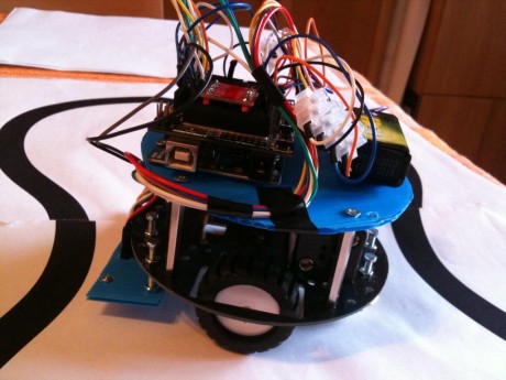
Linea is my first line follower based on Arduino.

A line follower is a robot for beginners. In fact it is very simple to build a line follower and only few components are required :

– a robot chassis

– IR sensors for line tracking (black or white line)

– two motors (servos or gear motors)

– an Arduino to drive the motors and to implement control logic

– Batteries, jumpers, screws and other hardware

If you use  gear motors it is important to use also a motors driver, because Arduino can’t feed the motors with the high current required.


IR SENSORS

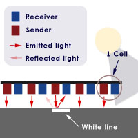
The sensors used in line follower robot are Infrared sensors and they are made with 2 different components:

– a light emitter

– a light receiver

When the emitter emits light, the light is reflected by the floor. If the line is white and the sensor is above the line, the white line reflect all the light, so it permits to understand that the sensor is effectively above the line. Instead if the sensor is over the black surface, the sensor doesn’t reflect the light, so we can understand that the sensor isn’t above the line.
If we have many IR sensors, knowing which sensor is above the line, lets to understand if the robot is going out from the middle of the line,  at the right or the left side. In the picture above are shown 5 sensors, but is not unusual to use 8 or 10 sensors. The minimum required is 3 sensor (left, straight, right).


The CONTROL

The robot, mostly if the line is curved, will go out of the path. It is important to teach to the robot how to maintain above the line. Usually, it is possible to do this with a motion control and the PID (Proportional-derivative-integral) control is the most famous. This control will try to compensate the error, i.e. the misalignment from the line. You can find some details about PID in wikipedia.

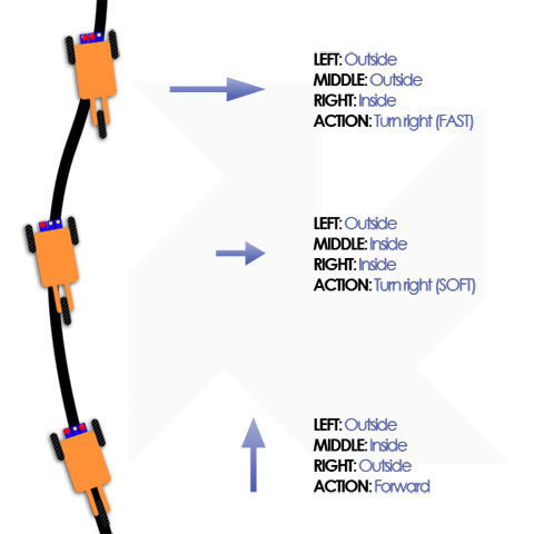
This picture shows the criteria used for the control:


The combined readings from the sensors are used to understand if the correction done by the control have to be hard or soft.


Linea – The line follower robot

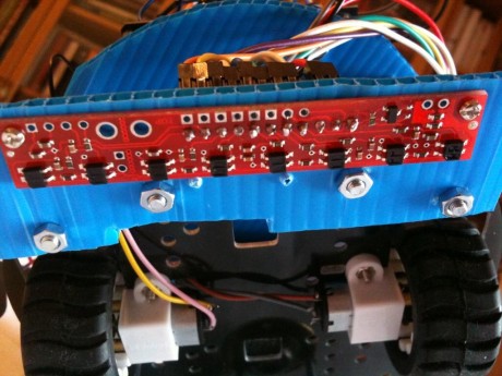
This robot was shown on the Arduino Day, in Rome (Italy), in April 2011 and  use a Pololu sensor with 8 IR leds ( link), very cheap (14 euros). It is offered with an Arduino library, made by Pololu. This library resolves all the interfacing problems with Arduino (yeah!).


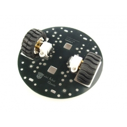
The robot chassis is build using a cheap DFRobot module (link) that for less than 30 euros, offers also 2 gear motors, 2 motor supports and 2 wheels:

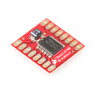
The motor driver is a Sparkfun module (link) , very very cheap (8 euros), that can feed up to 1.2A. It supports 2 gear motors and lets the PWM usage.

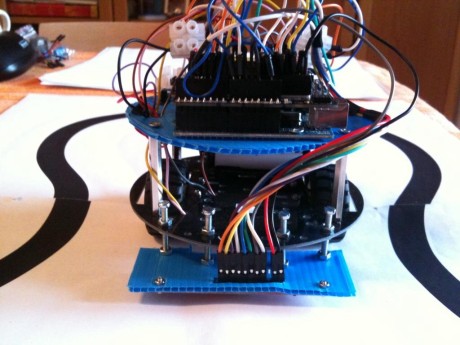
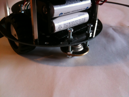
For my convenience I assembled the motor drivers on a breadboard shield, but it is enough a normal breadboard. Others components (ball caster, sensor support, batteries) are self made or bought in a hardware shop.

This is Linea:


Here Linea in action:


This is the code used:

#include <PololuQTRSensors.h>
// motor driver pin
#define out_STBY 6
#define out_B_PWM 9
#define out_A_PWM 3
#define out_A_IN2 4
#define out_A_IN1 5
#define out_B_IN1 7
#define out_B_IN2 8
#define motor_A 0
#define motor_B 1
#define motor_AB 2

#define NUM_SENSORS 8 // number of sensors used - numero di sensori usati
#define TIMEOUT 2500 // waits for 2500 us for sensor outputs to go low - aspetta 2500 us prima di mandare low i sensori
  //define QTR pololu sensor
PololuQTRSensorsRC qtrrc((unsigned char[]) {2, 12, 11, 10, 17, 16, 15, 14}
 , NUM_SENSORS, TIMEOUT, 255);
unsigned int sensors[NUM_SENSORS];
  void setup()
{
  Serial.begin(115200);
  // define motor drive output pin - definisci i pin di output del motore
  pinMode(out_STBY,OUTPUT);
  pinMode(out_A_PWM,OUTPUT);
  pinMode(out_A_IN1,OUTPUT);
  pinMode(out_A_IN2,OUTPUT);
  pinMode(out_B_PWM,OUTPUT);
  pinMode(out_B_IN1,OUTPUT);
  pinMode(out_B_IN2,OUTPUT);
  motor_standby(false);// motor stand-by off and stop - togli i motori dallo stand-by e fermali
  stopMotors();
  delay(2000);
  SensorCalibration(); // sensor calibration - calibra i sensori
  delay(2000);
}

void loop()
{
  follow_segment(); // follow the black line - segui la linea nera
}
// PID parameters
int Kp=120;
int Ki=100;
int Kd=100;
// follow the black line - segui la linea nera 
void follow_segment()
{
  int last_proportional = 0;
  long integral=0;
  int primo=0;
  int posizione = qtrrc.readLine(sensors); // read the IR sensors - leggi i sensori IR 
  long int proportional = posizione;
  int P = proportional * Kp/1000; // Proportional parameter 
  long int derivative = proportional - last_proportional; //Derivative parameter
  if (primo==0) // firt cycle set derivative to zero - al primo giro imposta il derivativo a zero
     {
      primo=1;
      derivative=0;
    }
  int D=derivative*Kd/1000;
  integral += proportional;
  int I=integral*Ki/1000; //integral parameter 
  // Remember the last position - ricorda l'ultima posizione
  last_proportional = proportional;
  int PID =P + I + D; //calculate the PID 
  // print some values on the serial port - scrivi qualche valore sulla seriale
  unsigned char zz;
   for (zz = 0; zz < NUM_SENSORS; zz++)
    {
      Serial.print(sensors[zz]);
      Serial.print(' ');
    }
    Serial.print(" position: ");
    Serial.print(posizione);
    Serial.print(" P:");
    Serial.print(P);
    Serial.print(" I:");
    Serial.print(I);
    Serial.print(" D:");
    Serial.print(D);
    Serial.print(" PID:");
    Serial.print(PID);
  // set the values for the motors based on the PID gain - setta i valori del motore basati sul PID
    const int maximum = 40; // the maximum speed
     if (PID > 0){
       if (PID > maximum) PID=maximum;
       motor_speed2(motor_B,maximum);
       motor_speed2(motor_A,maximum-PID);
      Serial.print(" Motore_B:");     Serial.print(maximum);
    Serial.print(" Motore_A:");      Serial.print(maximum-PID);
      }
      else {
       if (PID < -maximum) PID=-maximum;
       motor_speed2(motor_B,maximum+PID);
        motor_speed2(motor_A,maximum);
      Serial.print(" Motore_B:");     Serial.print(maximum+PID);
    Serial.print(" Motore_A:");      Serial.print(maximum);
      }
      Serial.println("");
}
// ------------------ stop the robot - ferma il robottino ----------------------- 
void stopMotors(){
  motor_brake(motor_A);
  motor_brake(motor_B);
}
// ------------------ Motor driver mgmt routines - routine per gestire i motori ----------------------- 
void motor_speed2(boolean motor, char speed) { //speed from 0 to 100
  if (motor == motor_A)
   speed = -speed;
  byte PWMvalue=0;
  PWMvalue = map(abs(speed),0,100,50,255); //anything below 50 is very weak
  if (speed > 0)
    motor_speed(motor,0,PWMvalue);
  else if (speed < 0)
    motor_speed(motor,1,PWMvalue);
  else {
    motor_coast(motor);
  }
}
void motor_speed(boolean motor, boolean direction, byte speed) { //speed from 0 to 255
  if (motor == motor_A) {
    if (direction == 0) {
      digitalWrite(out_A_IN1,HIGH);
      digitalWrite(out_A_IN2,LOW);
    } else {
      digitalWrite(out_A_IN1,LOW);
      digitalWrite(out_A_IN2,HIGH);
    }
    analogWrite(out_A_PWM,speed);
  } else {
    if (direction == 0) {
      digitalWrite(out_B_IN1,HIGH);
      digitalWrite(out_B_IN2,LOW);
    } else {
       digitalWrite(out_B_IN1,LOW);
      digitalWrite(out_B_IN2,HIGH);
    }
    analogWrite(out_B_PWM,speed);
  }
}
// stand-by motor
void motor_standby(boolean state) { //low power mode
  if (state == true)
    digitalWrite(out_STBY,LOW);
  else
    digitalWrite(out_STBY,HIGH);
}
// stop the motors
void motor_brake(boolean motor) {
  if (motor == motor_A) {
    digitalWrite(out_A_IN1,HIGH);
    digitalWrite(out_A_IN2,HIGH);
  } else {
    digitalWrite(out_B_IN1,HIGH);
    digitalWrite(out_B_IN2,HIGH);
  }
}
// motors coast - fai girare i motori in folle
void motor_coast(boolean motor) {
  if (motor == motor_A) {
    digitalWrite(out_A_IN1,LOW);
    digitalWrite(out_A_IN2,LOW);
    digitalWrite(out_A_PWM,HIGH);
  } else {
    digitalWrite(out_B_IN1,LOW);
     digitalWrite(out_B_IN2,LOW);
    digitalWrite(out_B_PWM,HIGH);
  }
}
// IR sensor calibration 
void SensorCalibration() {
  int counter, i;
  for (counter=0; counter<40; counter++)
  {
    if (counter < 10 || counter >= 30) {
      motor_speed2(motor_A,10);
      motor_speed2(motor_B,-10);
    }
    else   {
      motor_speed2(motor_A,-10);
      motor_speed2(motor_B,10);
    }
    qtrrc.calibrate();
    // Since our counter runs to 80, the total delay will be
    // 80*20 = 1600 ms.
    delay(20);
  }
     // print the calibration minimum values measured when emitters were on
    for (i = 0; i < NUM_SENSORS; i++)
  {
    Serial.print(qtrrc.calibratedMinimumOn[i]);
    Serial.print(' ');
  }
  Serial.println();
    // print the calibration maximum values measured when emitters were on
  for (i = 0; i < NUM_SENSORS; i++)
  {
    Serial.print(qtrrc.calibratedMaximumOn[i]);
    Serial.print(' ');
  }
  Serial.println();
  Serial.println();
  stopMotors();
  delay(2000);
}

Tags: , ,